| Welcome, Guest |
You have to register before you can post on our site.
|
| Forum Statistics |
» Members: 5,954
» Latest member: Eiji
» Forum threads: 6,522
» Forum posts: 53,855
Full Statistics
|
| Online Users |
There are currently 160 online users.
» 0 Member(s) | 155 Guest(s)
Applebot, Baidu, Bing, Google, Yandex
|
| Latest Threads |
Wheels needed for Set 772...
Forum: Part Requests
Last Post: Alfred Schmitz
Yesterday, 12:02
» Replies: 11
» Views: 3,051
|
47430
Forum: Parts Authoring
Last Post: Jeff Jones
2026-06-23, 15:13
» Replies: 1
» Views: 669
|
Part request: Antimatter'...
Forum: Part Requests
Last Post: Liam Moore
2026-06-23, 2:10
» Replies: 0
» Views: 189
|
Part 6333p01 not function...
Forum: Help
Last Post: Hageta
2026-06-22, 23:27
» Replies: 6
» Views: 436
|
Town, Trains and Paradisa...
Forum: Official Models
Last Post: Takeshi Takahashi
2026-06-22, 19:11
» Replies: 3
» Views: 4,361
|
minifig head print variat...
Forum: Parts Authoring
Last Post: Jeff Jones
2026-06-22, 18:28
» Replies: 0
» Views: 135
|
Ralph Wiggum Head Simpson...
Forum: Part Requests
Last Post: JuanVi
2026-06-22, 18:16
» Replies: 2
» Views: 225
|
113308 and 113309 (Guardi...
Forum: Part Requests
Last Post: Hageta
2026-06-22, 9:37
» Replies: 3
» Views: 322
|
Adding Minifig Categories
Forum: Official File Specifications/Standards
Last Post: Orion Pobursky
2026-06-21, 19:13
» Replies: 14
» Views: 1,338
|
Can't seem to submit Avat...
Forum: General LDraw.org Discussion
Last Post: Hylian Waffle
2026-06-21, 17:40
» Replies: 0
» Views: 176
|
|
|
| Patterned parts detail |
|
Posted by: Orion Pobursky - 2020-01-16, 17:32 - Forum: Parts Authoring
- Replies (4)
|
 |
There is a minor debate on the PT regarding patterns that go "all the way to the edge" of the part. Specifically these 2 parts:
https://www.ldraw.org/cgi-bin/ptdetail.c...70bp0n.dat
[/url][url=https://www.ldraw.org/cgi-bin/ptdetail.cgi?f=parts/3070bp0l.dat]https://www.ldraw.org/cgi-bin/ptdetail.cgi?f=parts/3070bp0l.dat
I have both of these part and am the author of one of them. I've looked at them and it appears the pattern does, indeed, go all the way to the curved edge. On high magification, you can see that there is a very small gap but this is negligible in my mind.
As far as I'm concerned, this is a non-issue. It's imperceptible to the end user and we have precedence for both ways. A cursory scan of part shows 8 1x2 tiles where we have patterns that abut the edge (3069bpx1, 3069bps7, 3069bpx1, 3069bps9, 3069bpf1, 3069bps4, 3069bps5, 3069bp09, 3069bp0a). I'm sure there are more examples with other part type. Whatever the part author chooses should be fine.
|

|
|
| James Jessiman Memorial Award for 2019 awarded to Gerald Lasser |
|
Posted by: Johann Eisner - 2020-01-13, 18:25 - Forum: LDraw.org Announcements
- Replies (5)
|
 |
The LDraw.org Steering Committee is pleased to announce that the 2019 James Jessiman Memorial Award (JJMA) recipient is Gerald Lasser.
Well, actually there should be a few lines about Gerald here,
but unfortunately I know too little about him or his career here at LDraw,
because I only been active here since a short time.
But what I can say for sure about Gerald is that he is a gifted parts author and has been supporting the LDraw team for many, many years.
Both as part author and as reviewer.
Therefore I would like to express my sincere thanks on behalf of the Steer Co. and the entire LDraw team for his work here.
More information on the JJMA can be found at: https://www.ldraw.org/article/222.html
Johann Eisner
On behalf of the LDraw.org Steering Committee
|
|
|
|
| Where do these renders come from? |
|
Posted by: CJ H. - 2020-01-13, 8:11 - Forum: General LDraw.org Discussion
- Replies (2)
|
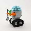 |
I've come across a few parts in Rebrickable that have 3D renders, but I can't find the part in LDraw or in Studio. For example: https://rebrickable.com/parts/10164pr000...top-print/
I'm pretty sure these are not cases where there is a part (official or unofficial) and it's just under a different number.
Does anyone have an idea where the underlying parts for these renders might come from? For the example above, it looks like BrickOwl has the same rendering, but I haven't found any documentation on where their renders come from.
I posted the same question on the Rebrickable forum a while back, but Simon, who was responsible for their part images, passed away recently.
As an aside, I have found many cases where there isn't a part (official or unofficial) in LDraw, but there is one in Studio. Why would that be?
Thanks.
|
|
|
|
|


![[Image: 250x250p.jpg?1577915651.8307977]](https://cdn.rebrickable.com/media/thumbs/parts/elements/6285587.jpg/250x250p.jpg?1577915651.8307977)

 )
)