Edges between floating vertices?


Edges between floating vertices?
#1
Guys,

honestly I'm a bit embarrassed - I really thought I knew all about authoring after all these years. However - I took the modelled head of the horse and created a flattened copy at x=0. I'd like to join every vertex at x=0 to X=a in the modelled head. Once I get all edges the modelled (main color) head will be deleted in order to get only the edges, which will be used as "altitude" guides for a patterned version.
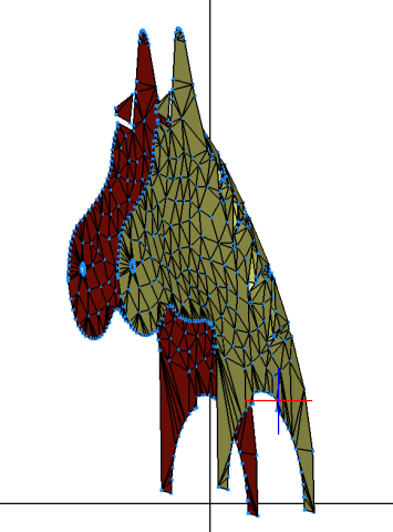
   

I could obviously do it manually but was wondering if it can be all done with just a few clicks. Any ideas?

w.
LEGO ergo sum
Reply
RE: Edges between floating vertices?
#2
I think I have an idea, but I'd like to experiment. Can you share your "source" file?

Quote:which will be used as "altitude" guides for a patterned version.
I don't understand the idea behind that...
Reply
RE: Edges between floating vertices?
#3
(2019-10-09, 12:05)Philippe Hurbain Wrote: I think I have an idea, but I'd like to experiment. Can you share your "source" file?

I don't understand the idea behind that...

I think... Willy means...he wants to use these Lines as a Basic Spline ...
Reply
RE: Edges between floating vertices?
#4
(2019-10-09, 11:10)Willy Tschager Wrote: Guys,

honestly I'm a bit embarrassed - I really thought I knew all about authoring after all these years. However - I took the modelled head of the horse and created a flattened copy at x=0. I'd like to join every vertex at x=0 to X=a in the modelled head. Once I get all edges the modelled (main color) head will be deleted in order to get only the edges, which will be used as "altitude" guides for a patterned version.


I could obviously do it manually but was wondering if it can be all done with just a few clicks. Any ideas?

w.

Wouldn't Pathtruder work with the path just being X=o to X=a?

So you want a template for the front view?
Reply
RE: Edges between floating vertices?
#5
I think I've got what you want, using Edger2 and YTruder


Code:
0 // start with this set of triangles

3 16 -6.3 0 2.1 -5.1 0 -1.15 -2.35 0 1.25
3 16 -6.3 0 2.1 -2.35 0 1.25 -3.05 0 4.05
3 16 -3.05 0 4.05 -2.35 0 1.25 -.15 0 3.85
3 16 -3.05 0 4.05 -.15 0 3.85 -.45 0 5.55
3 16 -.45 0 5.55 -.15 0 3.85 2.8 0 5.55
3 16 2.8 0 5.55 -.15 0 3.85 3.55 0 3.6
3 16 3.55 0 3.6 -.15 0 3.85 3.55 0 1.05
3 16 3.55 0 3.6 3.55 0 1.05 7 0 1.7
3 16 7 0 1.7 3.55 0 1.05 7.75 0 -.75
3 16 7.75 0 -.75 3.55 0 1.05 5.9 0 -3.5
3 16 5.9 0 -3.5 3.55 0 1.05 2.25 0 -4.6
3 16 5.9 0 -3.5 2.25 0 -4.6 5.6 0 -6.6
3 16 5.9 0 -3.5 5.6 0 -6.6 10.25 0 -6.5
3 16 5.9 0 -3.5 10.25 0 -6.5 11.85 0 -4

0 // DO an Edger2
0 // INCLUDE unmatched edges
0 // THis gets you this

2 4 10.25 0 -6.5 11.85 0 -4
2 4 -5.1 0 -1.15 -2.35 0 1.25
2 4 2.8 0 5.55 -.45 0 5.55
2 4 11.85 0 -4 5.9 0 -3.5
2 4 3.55 0 1.05 2.25 0 -4.6
2 4 2.25 0 -4.6 5.6 0 -6.6
2 4 3.55 0 3.6 2.8 0 5.55
2 4 -6.3 0 2.1 -5.1 0 -1.15
2 4 5.9 0 -3.5 7.75 0 -.75
2 4 5.6 0 -6.6 10.25 0 -6.5
2 4 -.45 0 5.55 -3.05 0 4.05
2 4 -.15 0 3.85 3.55 0 1.05
2 4 7 0 1.7 3.55 0 3.6
2 4 7.75 0 -.75 7 0 1.7
2 4 -3.05 0 4.05 -6.3 0 2.1
2 4 -2.35 0 1.25 -.15 0 3.85

0 // Now select the red lines and do a YTruder
0 // with DISTANCE 20
0 // Gets you this

2 24 -6.3 0 2.1 -6.3 20 2.1
2 24 -5.1 0 -1.15 -5.1 20 -1.15
2 24 -.15 0 3.85 -.15 20 3.85
2 24 3.55 0 1.05 3.55 20 1.05
2 24 2.25 0 -4.6 2.25 20 -4.6
2 24 5.6 0 -6.6 5.6 20 -6.6
2 24 10.25 0 -6.5 10.25 20 -6.5
2 24 11.85 0 -4 11.85 20 -4
2 24 5.9 0 -3.5 5.9 20 -3.5
2 24 7.75 0 -.75 7.75 20 -.75
2 24 7 0 1.7 7 20 1.7
2 24 3.55 0 3.6 3.55 20 3.6
2 24 2.8 0 5.55 2.8 20 5.55
4 16 2.25 0 -4.6 5.6 0 -6.6 5.6 20 -6.6 2.25 20 -4.6
4 16 5.6 0 -6.6 10.25 0 -6.5 10.25 20 -6.5 5.6 20 -6.6
4 16 10.25 0 -6.5 11.85 0 -4 11.85 20 -4 10.25 20 -6.5
4 16 11.85 0 -4 5.9 0 -3.5 5.9 20 -3.5 11.85 20 -4
4 16 5.9 0 -3.5 7.75 0 -.75 7.75 20 -.75 5.9 20 -3.5
4 16 7.75 0 -.75 7 0 1.7 7 20 1.7 7.75 20 -.75
4 16 7 0 1.7 3.55 0 3.6 3.55 20 3.6 7 20 1.7
4 16 3.55 0 3.6 2.8 0 5.55 2.8 20 5.55 3.55 20 3.6
4 16 2.8 0 5.55 -.45 0 5.55 -.45 20 5.55 2.8 20 5.55
4 16 -.45 0 5.55 -3.05 0 4.05 -3.05 20 4.05 -.45 20 5.55
4 16 -3.05 0 4.05 -6.3 0 2.1 -6.3 20 2.1 -3.05 20 4.05
4 16 -6.3 0 2.1 -5.1 0 -1.15 -5.1 20 -1.15 -6.3 20 2.1
4 16 -5.1 0 -1.15 -2.35 0 1.25 -2.35 20 1.25 -5.1 20 -1.15
4 16 -2.35 0 1.25 -.15 0 3.85 -.15 20 3.85 -2.35 20 1.25
4 16 -.15 0 3.85 3.55 0 1.05 3.55 20 1.05 -.15 20 3.85
4 16 3.55 0 1.05 2.25 0 -4.6 2.25 20 -4.6 3.55 20 1.05
5 24 -.45 0 5.55 -.45 20 5.55 -3.05 0 4.05 2.8 0 5.55
5 24 -3.05 0 4.05 -3.05 20 4.05 -6.3 0 2.1 -.45 0 5.55
5 24 -2.35 0 1.25 -2.35 20 1.25 -.15 0 3.85 -5.1 0 -1.15
Reply
RE: Edges between floating vertices?
#6
Ah, I didn't got what Willy wanted. If indeed the purpose is to create a wall surface around an existing top surface, Gerald method is right. See also this very old tutorial http://philohome.com/isecalc/yttut.htm (but of course use more modern tools!), or this more modern one: https://www.wiki.ldraw.org/index.php?tit..._shape_one (granted, a bit different: since the top here is not flat, we must use projection on plane in ytruder instead of translation by distance).
Reply
RE: Edges between floating vertices?
#7
(2019-10-09, 12:05)Philippe Hurbain Wrote: I think I have an idea, but I'd like to experiment. Can you share your "source" file?

I don't understand the idea behind that...

I don't wanna "wall" the two shapes. I know how to do that. I'd like to have lines from every single vertex to x=a. I added a few manually in the example.


.dat   Head1.dat (Size: 56.75 KB / Downloads: 5)

Once I have those I remove all color 16 and bring in my pattern:


.dat   Head_Pattern_11.10.2019.dat (Size: 59.16 KB / Downloads: 5)

Now I move all vertices from the pattern to a position where the lines start sticking through to get the shape right. I cannot simply project the pattern onto the current head as it would create an ton of tiny, tiny triangles.

w.
LEGO ergo sum
Reply
RE: Edges between floating vertices?
#8
OK, I see what you need and understand the purpose. Thinking...
Reply
RE: Edges between floating vertices?
#9
(2019-10-11, 18:27)Philippe Hurbain Wrote: OK, I see what you need and understand the purpose. Thinking...
Got it... Write up tomorrow!


Attached Files
.dat   head1out.dat (Size: 36.78 KB / Downloads: 6)
Reply
RE: Edges between floating vertices?
#10
Ah, I think, I got what you want.

What I usually do in such cases I draw immediately on the template.
  • I would import the relief into LDPC.
  • Start drawing the pattern optimized to the Reference Lines (so using Ctrl-T and Ctrl-P to move the vertices to the edges, respectively the  vertices of the template)
  • At the places where you used circles, I would draw them as well without taking the Reference Lines into account, but afterwards slice it manually with the CSG tool as the SlicerPro is sometimes giving issues when triangles are getting too small.
I started doing this since I made the Monster Fighter's Train Dish with Slicer Pro, gave me about a million Micro-triangles that I had to mend together. So I find it much easier to draw with the reference lines in place.
Reply
RE: Edges between floating vertices?
#11
I did a screen capture to show you how I would do it

https://youtu.be/tBhhkdJSJUc
Reply
RE: Edges between floating vertices?
#12
(2019-10-11, 20:09)Gerald Lasser Wrote: Ah, I think, I got what you want.

What I usually do in such cases I draw immediately on the template.
  • I would import the relief into LDPC.
  • Start drawing the pattern optimized to the Reference Lines (so using Ctrl-T and Ctrl-P to move the vertices to the edges, respectively the  vertices of the template)
  • At the places where you used circles, I would draw them as well without taking the Reference Lines into account, but afterwards slice it manually with the CSG tool as the SlicerPro is sometimes giving issues when triangles are getting too small.
I started doing this since I made the Monster Fighter's Train Dish with Slicer Pro, gave me about a million Micro-triangles that I had to mend together. So I find it much easier to draw with the reference lines in place.
This is more or less the way I do 3D patterns.
  • import shape in LDPC
  • import background image
  • Create vertices (with vertices creation tool) nearby the point where a color boundary of the image crosses a template line.
  • Press ctrl+t immediately to move the vertex exactly on template line
  • when all these intersection vertices are created, I triangulate the pattern, adding additionnal vertices where needed with the triangulation tool. Remains tedious, but that's the most efficient way I found.
Otherwise... if you want to recreate create the patterned head without slicing (which makes sense here since the pattern is dense and head shape triangulation is random):
  • in LDPE, add the head shape to your flat pattern
  • Select the pattern and project it on the head: action -> merge to nearest surface(direction) and choose +x direction
  • Delete head shape reference (and correct the vertex that fell outside that reference)
  • Add condlines... (and change them to edge lines in the mane!)


Attached Files Thumbnail(s)
   

.dat   headpat-a.dat (Size: 59.19 KB / Downloads: 1)
.dat   headpat-b.dat (Size: 95.93 KB / Downloads: 1)
.dat   headpat-c.dat (Size: 95.9 KB / Downloads: 1)
.dat   headpat-d.dat (Size: 250.05 KB / Downloads: 1)
Reply
RE: Edges between floating vertices?
#13
(2019-10-11, 20:09)Gerald Lasser Wrote: Ah, I think, I got what you want.

What I usually do in such cases I draw immediately on the template.
  • I would import the relief into LDPC.
  • Start drawing the pattern optimized to the Reference Lines (so using Ctrl-T and Ctrl-P to move the vertices to the edges, respectively the  vertices of the template)
  • At the places where you used circles, I would draw them as well without taking the Reference Lines into account, but afterwards slice it manually with the CSG tool as the SlicerPro is sometimes giving issues when triangles are getting too small.
I started doing this since I made the Monster Fighter's Train Dish with Slicer Pro, gave me about a million Micro-triangles that I had to mend together. So I find it much easier to draw with the reference lines in place.

This is how I usually do it as well. I also tried to do it for the horse but it gets so laborious (and messy) that I prefer adjusting my pattern in 3D. There is no benefit from trying to follow the mesh.


w.
LEGO ergo sum
Reply
RE: Edges between floating vertices?
#14
(2019-10-11, 18:39)Philippe Hurbain Wrote: Got it... Write up tomorrow!

Philo,

this looks perfect! how did you do it?

w.
LEGO ergo sum
Reply
RE: Edges between floating vertices?
#15
(2019-10-14, 10:24)Willy Tschager Wrote: this looks perfect! how did you do it?
Sorry, I thought the other methods for this pattern would be better (did you have a close look on my projection method here: https://forums.ldraw.org/thread-23710-po...l#pid34290 ?)

. So...
- Open the shape in LDPE, and with Edger2 tool create lines/condlines everywhere (set flat surface maximum angle to 0). Create unmatched edges too.
- Select everything (ctrl+A) and convert condlines to edge lines (C2L button).
- Select everything again, launch Ytruder. Projection on plane, value=0, condline threshold=0 (edge lines everywhere), operation axis X
- Select one surface, Select -> uncheck vertices/lines/condlines, then select -> all shown. Delete key to let only lines
- Slightly more tricky part: view head in front view, manually select all top edge lines with a marquee, hit delete key.

Done.

Edit: This process creates a lot of duplicated lines, may need to cleanup in text window.
Reply
RE: Edges between floating vertices?
#16
The horse head is now at the PT:


https://www.ldraw.org/cgi-bin/ptdetail.c...492pw1.dat

In the end the way I had in mind didn't work out as plant - still too much work to do and the result wasn't satisfying.

* Moved the projection of the pattern at x=10
* Added Philo's edge file as subpart
* Used the outer rim of Philo's file to get the border at the right distance
* Brought in the existing 4492s00.dat - Animal Horse Head Side Surface
* Moved sections of the pattern (mostly based on color) very close to the surface
* "Merge To Nearest Face"
* CRTL+E of those vertices which were reused in the pattern from the imported template

w.
LEGO ergo sum
Reply
RE: Edges between floating vertices?
#17
And here is the rest of it:


https://www.ldraw.org/cgi-bin/ptdetail.c...pw1c00.dat

w.
LEGO ergo sum
Reply
RE: Edges between floating vertices?
#18
Wow! That's an incredible pattern!
Reply
RE: Edges between floating vertices?
#19
Yee Haw!!!


https://www.ldraw.org/cgi-bin/ptdetail.c...pw2c00.dat

w.
LEGO ergo sum
Reply
RE: Edges between floating vertices?
#20
(2020-03-11, 14:11)Willy Tschager Wrote: Yee Haw!!!


https://www.ldraw.org/cgi-bin/ptdetail.c...pw2c00.dat

w.
Gorgeous!
Reply
RE: Edges between floating vertices?
#21
(2020-03-11, 14:46)Philippe Hurbain Wrote: Gorgeous!

Thx. Now I feel ready to tackle this ... well almost:

[Image: x172px1.png]

w.
LEGO ergo sum
Reply
« Next Oldest | Next Newest »


Forum Jump:


Users browsing this thread: 8 Guest(s)