Thread for the inaugural year of Technic sets.
Technic 1977
853/956 - Auto Chassis (main model)
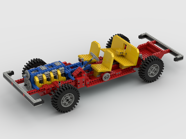
My first model submission!
No known errors, but a few spots are "unbuildable" in LDraw, because they depend on the natural tolerance of physical plastic (common among early Technic/Expert Builder sets):
My first model submission!
No known errors, but a few spots are "unbuildable" in LDraw, because they depend on the natural tolerance of physical plastic (common among early Technic/Expert Builder sets):
- Where the steering tie rods join the control arms, the pins are not "in click" with the 2x4 Technic plates.
- The inclined 1x8 Technic bricks of the steering column are slightly out of alignment at their upper connection point.
- The rear suspension "struts" are well out of alignment at their upper connection point, such that the 4L axles are considerably compressed into the toggle joints.
In equipement 1 the driving axle
is placed too high, it collides with top plate and doesn't enter in the hole of bottom plate.
Also, since the model is shown with equipment 1, I think that the attachment beams of tractor should be configured/rotated so that the small wheels of equipment 1 sit on floor (and so that the top 40t gear properly mesh with driving crown gear of tractor)
Code:
1 0 -25.5 -48 -5 0 -1 0 1 0 0 0 0 1 3705.datAlso, since the model is shown with equipment 1, I think that the attachment beams of tractor should be configured/rotated so that the small wheels of equipment 1 sit on floor (and so that the top 40t gear properly mesh with driving crown gear of tractor)
(2020-03-21, 8:26)Philippe Hurbain Wrote: In equipement 1 the driving axleHello Philippe,
is placed too high, it collides with top plate and doesn't enter in the hole of bottom plate.Code:1 0 -25.5 -48 -5 0 -1 0 1 0 0 0 0 1 3705.dat
Also, since the model is shown with equipment 1, I think that the attachment beams of tractor should be configured/rotated so that the small wheels of equipment 1 sit on floor (and so that the top 40t gear properly mesh with driving crown gear of tractor)
Thanks for the comments. Apologies for the 'mess'. I clearly missed some clean-up actions.
This file should have corrected all your points and more I found myself.
When get files added to the overall list of official models?
Regards Allard
(2020-03-21, 13:31)aefferen Wrote: Hello Philippe,
Thanks for the comments. Apologies for the 'mess'. I clearly missed some clean-up actions.
This file should have corrected all your points and more I found myself.
When get files added to the overall list of official models?
Regards Allard
Still looks like some gears not meshing properly in the implement—in the first place, the whole implement is about 5 LDU off-center in the X direction. Then, the top 40t gear would have to be rotated by half a tooth to mesh with the crown gear. Finally, the two side "blades" of the implement will have to be rotated to mesh with the center one (which should end up being correctly oriented once the above problem is fixed).
Also, I spotted some extraneous 1x4 beams attached to the rear axles of the tractor, duplicating ones found in the lever-1 submodel. And, is there any particular reason to have the model's origin (0,0,0) so far away?
Finally, the steering column isn't fitting inside the 1x2 beams that hold it—this is always a tricky problem with these sets. And something's wrong up front, where one of the 8t gears is colliding with the 1x2 brick holding the axle. Looks like both gears just need to be slid backward.
Sorry to pick apart so much! Technic models are definitely challenging because of stuff like this, but that's where the fun (?) is with them.
 And I've certainly had invaluable help from other members of this forum in solving some of these challenges. You're welcome to have a look at my version of the tractor model (attached) if it's useful at all.
As for when models get added, I think it's a weekly process, though in my experience it seems to be quicker than that, once everything's compliant of course. On that note, the OMR spec does have guidance about file structure for sets with alternate builds—would that apply to the different attachments in a set like this? If so, I guess there should be a separate MPD file for each version, named according to which implement is attached—but good luck figuring out which real-world implements each one is supposed to represent!

 952 Tractor.ldr (Size: 41.09 KB / Downloads: 5)
(2020-03-21, 16:29)N. W. Perry Wrote: Still looks like some gears not meshing properly in the implement—in the first place, the whole implement is about 5 LDU off-center in the X direction. Then, the top 40t gear would have to be rotated by half a tooth to mesh with the crown gear. Finally, the two side "blades" of the implement will have to be rotated to mesh with the center one (which should end up being correctly oriented once the above problem is fixed).Hello NW Perry,
Also, I spotted some extraneous 1x4 beams attached to the rear axles of the tractor, duplicating ones found in the lever-1 submodel. And, is there any particular reason to have the model's origin (0,0,0) so far away?
Finally, the steering column isn't fitting inside the 1x2 beams that hold it—this is always a tricky problem with these sets. And something's wrong up front, where one of the 8t gears is colliding with the 1x2 brick holding the axle. Looks like both gears just need to be slid backward.
Sorry to pick apart so much! Technic models are definitely challenging because of stuff like this, but that's where the fun (?) is with them.And I've certainly had invaluable help from other members of this forum in solving some of these challenges. You're welcome to have a look at my version of the tractor model (attached) if it's useful at all.
As for when models get added, I think it's a weekly process, though in my experience it seems to be quicker than that, once everything's compliant of course. On that note, the OMR spec does have guidance about file structure for sets with alternate builds—would that apply to the different attachments in a set like this? If so, I guess there should be a separate MPD file for each version, named according to which implement is attached—but good luck figuring out which real-world implements each one is supposed to represent!
Thanks a lot for your comments. I am surprised to see 2 remarks I can't place after almost using MLcad for 10 years.
1. the whole implement is about 5 LDU off-center in the X direction; I don't know what this means? I am not aware that you can place a model somewhere specific.
2. [color=#333333][size=small][font=Tahoma, Verdana, Arial, sans-serif]model's origin (0,0,0) so far away; probably same as point 1. I will try to find out in MLcad where you can adjust these settings.
3. Regarding the gears, I never do the meshing of the gears, was not aware that is necessary.
4. I will read the guidance, I only used the MPDcenter check tool.
To summarize I have some home work to do!!
Thanks again, much appreciated.
Regards Allard[/font][/size][/color]
RE: Technic 1977
2020-03-26, 4:06 (This post was last modified: 2020-03-26, 4:09 by N. W. Perry. Edit Reason: for clarity )
2020-03-26, 4:06 (This post was last modified: 2020-03-26, 4:09 by N. W. Perry. Edit Reason: for clarity )
(2020-03-25, 19:19)aefferen Wrote: Hello NW Perry,
Thanks a lot for your comments. I am surprised to see 2 remarks I can't place after almost using MLcad for 10 years.
1. the whole implement is about 5 LDU off-center in the X direction; I don't know what this means? I am not aware that you can place a model somewhere specific.
2. [color=#333333][size=small][font=Tahoma, Verdana, Arial, sans-serif]model's origin (0,0,0) so far away; probably same as point 1. I will try to find out in MLcad where you can adjust these settings.
3. Regarding the gears, I never do the meshing of the gears, was not aware that is necessary.
4. I will read the guidance, I only used the MPDcenter check tool.
To summarize I have some home work to do!!
Thanks again, much appreciated.
Regards Allard[/font][/size][/color]
1. Here's a screenshot from LDCad showing what I mean:
I've displayed a grid at a 5 LDU resolution (and hidden one 1x8 beam for clarity). Looking down from above, the tractor itself is visible at bottom, and the attachment (your submodel "equipment1") is at top. The vertical white grid line shows the center of the model; notice that the main tractor is properly centered, but "equipment1" is one grid square too far to the left. Since its current position is <-320 16 1625>, all that's necessary is to add 5 to the X coordinate, so: <-315 16 1625>.
2. Not sure how it's done in MLCad since I don't have the program, but it should be quick and easy, and worth doing. Depending on what program others use to view your model, it might give strange results when we try to rotate the view, if it's set to rotate around the model's origin. (I personally like to set the Y-origin at the lowest physical point of the model, so it sits on the "floor" and doesn't appear to be floating when I go to render the model, but that's not the only way to do it.)
3. Meshing gears isn't necessary for OMR purposes, it's really just your own discretion as a modeler. While I always mesh everything when building Technic models in LDraw, it was a presumption on my part that most other modelers do as well, but perhaps the practice isn't as widespread as I guessed. (It seems many of the good folks here put their considerable skills into tackling behind-the-scenes issues, allowing less accomplished LDraw-ers like me to focus on things like meshing gears.) :-)
4. Yes, MPDCenter won't know if you're building a set that has alternate builds, but there are specific guidelines for naming those files. However, I'm not actually sure how that would apply here—most Technic sets have 2 or more totally different models you can build, but in this case it's one model with a variety of alternate attachments (and then I think the set has a couple of fully standalone alternate builds as well).
So I'd open that question to the community as to what's the most appropriate naming scheme for this set. I think my personal solution would be to have all the attachments included as submodels in the final building step, at the appropriate positions, and then to "comment out" all but the one currently being displayed. All of that together would then be named "851 - Tractor - Main model.mpd". Then if you decided to build the two standalone models, they would be named "851 - Tractor - Power saw.mpd" and "851 - Tractor - Wood splitter.mpd"—or whatever you determine those models to actually represent!

(2020-03-26, 4:06)N. W. Perry Wrote: 1. Here's a screenshot from LDCad showing what I mean:Hello N. W. Perry,
I've displayed a grid at a 5 LDU resolution (and hidden one 1x8 beam for clarity). Looking down from above, the tractor itself is visible at bottom, and the attachment (your submodel "equipment1") is at top. The vertical white grid line shows the center of the model; notice that the main tractor is properly centered, but "equipment1" is one grid square too far to the left. Since its current position is <-320 16 1625>, all that's necessary is to add 5 to the X coordinate, so: <-315 16 1625>.
2. Not sure how it's done in MLCad since I don't have the program, but it should be quick and easy, and worth doing. Depending on what program others use to view your model, it might give strange results when we try to rotate the view, if it's set to rotate around the model's origin. (I personally like to set the Y-origin at the lowest physical point of the model, so it sits on the "floor" and doesn't appear to be floating when I go to render the model, but that's not the only way to do it.)
3. Meshing gears isn't necessary for OMR purposes, it's really just your own discretion as a modeler. While I always mesh everything when building Technic models in LDraw, it was a presumption on my part that most other modelers do as well, but perhaps the practice isn't as widespread as I guessed. (It seems many of the good folks here put their considerable skills into tackling behind-the-scenes issues, allowing less accomplished LDraw-ers like me to focus on things like meshing gears.) :-)
4. Yes, MPDCenter won't know if you're building a set that has alternate builds, but there are specific guidelines for naming those files. However, I'm not actually sure how that would apply here—most Technic sets have 2 or more totally different models you can build, but in this case it's one model with a variety of alternate attachments (and then I think the set has a couple of fully standalone alternate builds as well).
So I'd open that question to the community as to what's the most appropriate naming scheme for this set. I think my personal solution would be to have all the attachments included as submodels in the final building step, at the appropriate positions, and then to "comment out" all but the one currently being displayed. All of that together would then be named "851 - Tractor - Main model.mpd". Then if you decided to build the two standalone models, they would be named "851 - Tractor - Power saw.mpd" and "851 - Tractor - Wood splitter.mpd"—or whatever you determine those models to actually represent!
Thanks again for your elaborate reply much appreciated.
point 1. After some investigation I understood what you meant. This is fixed now. Further more I am going through the model now part by part and do find several omissions. So lot op corrections to do.
Point 2. Still didn't find in MLcad how to solve that issue. I discovered now what you mean. I did find a function to sow the center point and it is way outside the model. Problem is I don't know how that happened. More work to do.
Point 3. Currently busy to mesh the gears, just to do that for once.
Point 4. I found the guidelines but these are pretty elaborate so need to find a quiet moment to read them.
All in all again a well appreciated feedback.
Best regards Allard
(2020-03-27, 18:51)aefferen Wrote: Hello N. W. Perry,Adjusted file.
Thanks again for your elaborate reply much appreciated.
point 1. After some investigation I understood what you meant. This is fixed now. Further more I am going through the model now part by part and do find several omissions. So lot op corrections to do.
Point 2. Still didn't find in MLcad how to solve that issue. I discovered now what you mean. I did find a function to sow the center point and it is way outside the model. Problem is I don't know how that happened. More work to do.
Point 3. Currently busy to mesh the gears, just to do that for once.
Point 4. I found the guidelines but these are pretty elaborate so need to find a quiet moment to read them.
All in all again a well appreciated feedback.
Best regards Allard
1. corrected
2. managed to find out how to correct this. You are right it is much easier to move the 3D model now.
3. Gears are meshed.
4. double checked against the guidelines. Didn't find directions for equipment so left it as it is.
(2020-03-27, 20:17)aefferen Wrote: Adjusted file.
1. corrected
2. managed to find out how to correct this. You are right it is much easier to move the 3D model now.
3. Gears are meshed.
4. double checked against the guidelines. Didn't find directions for equipment so left it as it is.
You can always go ahead and submit it, and if the name does need to be changed, they may just do it for you. (Or let it pass—the guidelines are generally considered just that, not firm rules.)
There's still the one little collision with the 8t gears in Step 6—it'll be a quick fix! But everything else is certainly looking pretty good. :-)
(2020-03-28, 2:30)N. W. Perry Wrote: You can always go ahead and submit it, and if the name does need to be changed, they may just do it for you. (Or let it pass—the guidelines are generally considered just that, not firm rules.)Hello Perry,
There's still the one little collision with the 8t gears in Step 6—it'll be a quick fix! But everything else is certainly looking pretty good. :-)
I know I can't get it right. It seems the crown gear is simply a 'hair' to deep. See attached file. I aligned both neatly and then it shows the crown wheel sticks beyond the 1x2 tech brick.
I assumed you meant step 6 in the original building instruction.
regards Allard
(2020-04-03, 16:33)aefferen Wrote: Hello Perry,
I know I can't get it right. It seems the crown gear is simply a 'hair' to deep. See attached file. I aligned both neatly and then it shows the crown wheel sticks beyond the 1x2 tech brick.
I assumed you meant step 6 in the original building instruction.
regards Allard
I must have meant step 6 in your model—I'm referring to the two 8-tooth gears that mesh with the steering rack. They're colliding with the 1x2 brick that is their bearing, and just need to be slid back along their axle. (In the original instructions, they're added in step 12.)
850/950 Fork-Lift Truck (1977)
Original model by Merlijn, added missing axle, corrected tyre colour, and rearranged submodels based on movement
 850-1 - Fork-Lift Truck.mpd (Size: 12.21 KB / Downloads: 5)
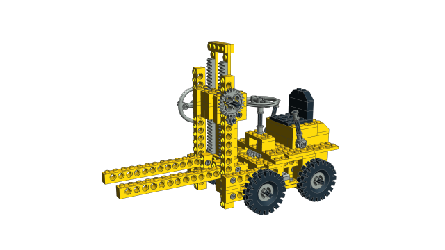
OMR compliant
Missing items: none
Known errors: slight (2 LDU on each side) collision, between the vertical beam, bottom pins and top axles
Original model by Merlijn, added missing axle, corrected tyre colour, and rearranged submodels based on movement
 850-1 - Fork-Lift Truck.mpd (Size: 12.21 KB / Downloads: 5)
OMR compliant
Missing items: none
Known errors: slight (2 LDU on each side) collision, between the vertical beam, bottom pins and top axles
850/950 Fork-Lift Truck - B-Model Lift
Original model by Merlijn, added missing parts, corrected tyre colour
 850-1 - Fork-Lift Truck - Lift.mpd (Size: 6.67 KB / Downloads: 3)
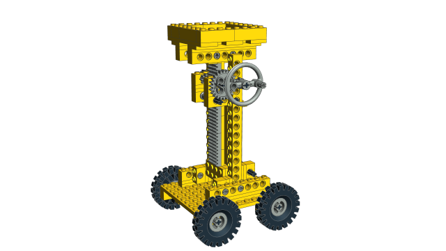
OMR compliant
Missing items: none
Original model by Merlijn, added missing parts, corrected tyre colour
 850-1 - Fork-Lift Truck - Lift.mpd (Size: 6.67 KB / Downloads: 3)
OMR compliant
Missing items: none
(2024-02-04, 13:28)Takeshi Takahashi Wrote: Known errors: slight (2 LDU on each side) collision, between the vertical beam, bottom pins and top axles
Ah, yes…you have to scale down the tower of 2x2 bricks a little bit in order for it to fit properly. (You can either spread the 2 LDU across all seven bricks equally, or as I did, just make two of them 1 LDU shorter and hide them in the middle somewhere.)

Also, you'll find that in real life, the fork assembly isn't perfectly perpendicular, but sits at a slight angle inside its mechanism. And of course the whole thing does tend to bind up a bit; it's just one of those cases where the real-world model depends on some amount of physical flexibility that LDraw simply doesn't represent. That was common in early Technic, after all!
(2024-02-05, 21:35)N. W. Perry Wrote: Ah, yes…you have to scale down the tower of 2x2 bricks a little bit in order for it to fit properly. (You can either spread the 2 LDU across all seven bricks equally, or as I did, just make two of them 1 LDU shorter and hide them in the middle somewhere.)
Also, you'll find that in real life, the fork assembly isn't perfectly perpendicular, but sits at a slight angle inside its mechanism. And of course the whole thing does tend to bind up a bit; it's just one of those cases where the real-world model depends on some amount of physical flexibility that LDraw simply doesn't represent. That was common in early Technic, after all!
Yes, I checked the dimensions again and again...but reached no exact solution. The distance between the upper pin and the lower axle is 18 plates high (=144 LDU) every time I counted, on the other hand the hole pitch is apparently 1 stud and the distance should be 140 LDU...??? Thus, I gave up.
The C-model (Grader) has also a nearly illegal build (?) like this...
850/950 Fork-Lift Truck - C-Model Grader
Original model by Merlijn, corrected tyre colour, and rearranged submodels based on movement
 850-1 - Fork-Lift Truck - Grader.mpd (Size: 9.58 KB / Downloads: 3)
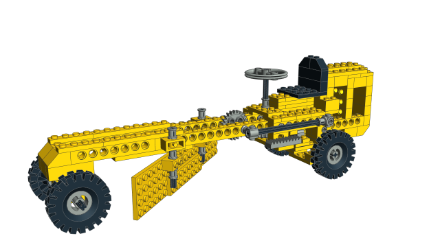
OMR compliant
Missing items: none
Known errors: The blade is not connected sufficiently to the body frame (in real life it's owing to part flexibility)
Original model by Merlijn, corrected tyre colour, and rearranged submodels based on movement
 850-1 - Fork-Lift Truck - Grader.mpd (Size: 9.58 KB / Downloads: 3)
OMR compliant
Missing items: none
Known errors: The blade is not connected sufficiently to the body frame (in real life it's owing to part flexibility)
851 - Tractor
2024-02-07, 15:35 (This post was last modified: 2024-02-10, 14:05 by Takeshi Takahashi.)
2024-02-07, 15:35 (This post was last modified: 2024-02-10, 14:05 by Takeshi Takahashi.)
851/952 Tractor - B-Model Crank Machine 1
 851-1 - Tractor - Crank Machine 1.mpd (Size: 3.86 KB / Downloads: 3)
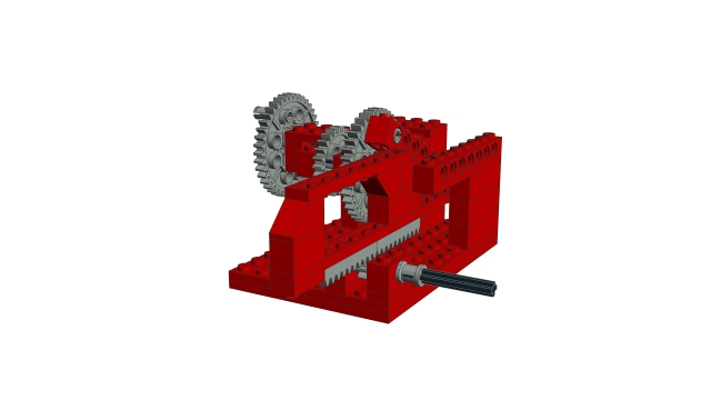
OMR compliant
Missing items: none
 851-1 - Tractor - Crank Machine 1.mpd (Size: 3.86 KB / Downloads: 3)
OMR compliant
Missing items: none
851/952 Tractor - C-Model Crank Machine 2
 851-1 - Tractor - Crank Machine 2.mpd (Size: 4.84 KB / Downloads: 3)
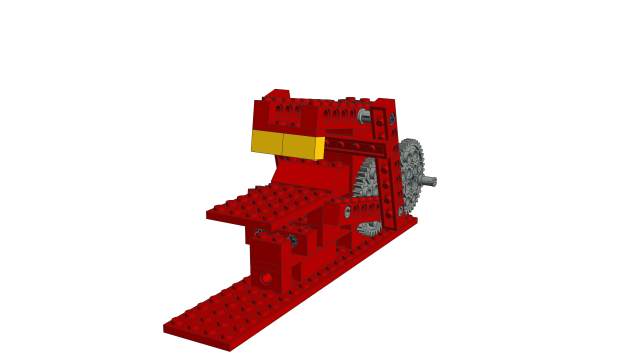
OMR compliant
Missing items: none
 851-1 - Tractor - Crank Machine 2.mpd (Size: 4.84 KB / Downloads: 3)
OMR compliant
Missing items: none
(2024-02-10, 2:58)N. W. Perry Wrote: I feel like these last two would be "simple" enough to try out LDCad's new interactive animation feature—for those clever enough to do so.
(By the way, why does the first crank machine have a transparent 1x2 brick? Is that in the file itself, or just the preview image?)
Yes, it's very nice to be animated!!
Thanks for pointing out the wrong colour.
The purpose was to adjust the angle of the rack and I've forgotten to set it back again.
852/954 Helicopter - B Model Prop Plane
 852-1 - Helicopter - Prop Plane.mpd (Size: 9.31 KB / Downloads: 3)
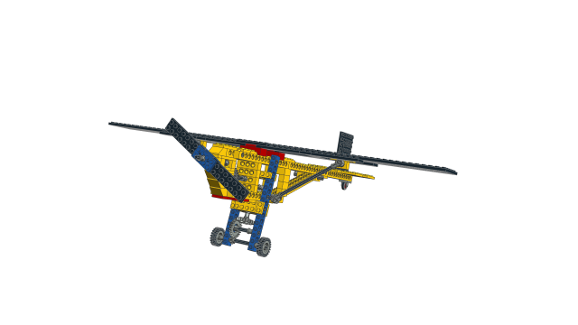
OMR compliant
Missing items: none
Known errors: Slight collisions at pin/axle connections (in real life it's owing to part flexibility)
 852-1 - Helicopter - Prop Plane.mpd (Size: 9.31 KB / Downloads: 3)
OMR compliant
Missing items: none
Known errors: Slight collisions at pin/axle connections (in real life it's owing to part flexibility)
853/956 Car Chassis - B Model Go Kart
 853-1 - Car Chassis - Go Kart.mpd (Size: 19.24 KB / Downloads: 3)
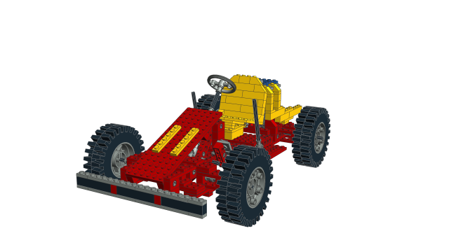
OMR compliant
Missing items: none
Known errors: Slight collisions at pin/axle connections (in real life it's owing to part flexibility)
 853-1 - Car Chassis - Go Kart.mpd (Size: 19.24 KB / Downloads: 3)
OMR compliant
Missing items: none
Known errors: Slight collisions at pin/axle connections (in real life it's owing to part flexibility)
« Next Oldest | Next Newest »
Users browsing this thread: 3 Guest(s)


 (Sometimes, I wish it would…)
