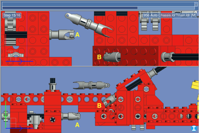
Since I got such quick and helpful advice on my piston rod question, here is my next challenge: universal joints!
Specifically, how do I work out the compound angles of a double u-joint connection? See the image below, where I need to connect axle A to axle B by using the short connecting axle that's floating nearby.

Here are some parameters:
Looking forward to everyone's suggestions!
Specifically, how do I work out the compound angles of a double u-joint connection? See the image below, where I need to connect axle A to axle B by using the short connecting axle that's floating nearby.
Here are some parameters:
- Axle A is oriented parallel the model's Z axis; axle B is oriented at an angle to it. The connector will have to be rotated in both the X and Y directions, but you can't just set one and then the other, because changing either affects both. I'm guessing the 't' word, trigonometry, will come in again here, but because of the compound angle, I'm not sure where to place the triangles.
- Axles A and B are rotated 22.5 degrees with respect to their longitudinal axes; my assumption is that the U-joint will transmit the same angle to the connector axle, and that while this rotation needs to be accounted for, it won't change the method needed to determine the connector angle.
- I guess I need to determine the rotation of the U-joint hubs at A and B, around both of their local X and Y axes. Again, my assumption is that the hubs themselves, however they may be rotated, will always remain at the same coordinates in absolute space; that is, they always form the point around which the connector axle is angled at each end.
- The end of the axle at B may need to be slid downward along its own longitudinal axis in order to correctly intersect the connector axle; this unknown position makes the trigonometry harder to figure out for me.
Looking forward to everyone's suggestions!


![[Image: thinking-face_1f914.png]](https://emojipedia-us.s3.dualstack.us-west-1.amazonaws.com/thumbs/120/google/223/thinking-face_1f914.png)
![[Image: g78ZGba.png]](https://i.imgur.com/g78ZGba.png)
![[Image: lHBXfV9.png]](https://i.imgur.com/lHBXfV9.png)


 )
) While reading through the script to figure out the necessary math, I noticed this line: