Hello everyone,
maybe the *.conn file format is already known but in case its not you can find the description below. I’m also referring partly to the thread “Studio Connectivity Data“ where the question was asked how the *.conn file format is defined.
Connectivity files, e.g., the file definition is actually not too complicated to understand. However, it is more complicated as the collision files just because there are more of them and they are encrypted.
It is true that Part Designer converts the *.conn files -contrary to the *.col files- to a binary format (due to whatever reason). But this does not mean that you cannot access the information, you just have to use a trick. If you generate a part file in Part Designer and store it as *.part it contains all information about the brick. The geometry, the connectivity info and -hidden in the part geometry- the collision data. To see the connectivity info in human-readable format only thing you have to do: Start with a new part but only add connectivity elements (no geometry). In the part editor you will see an empty workspace but in the connectivity editor you can see the connectivity element. If you store this part now as *.part you can open and read it in a text editor (the conversion to binary takes places during export; not internally). From here it is rather a matter of changing the individual values/variables in *.part file and check what are the consequences. Below an image from the STUD connectivity element e.g. the file format:

Figure 1.1: Connectivity file format for the STUD connectivity element (associated *.part file)
I’ve been playing around with these values and compared it with the other connectivity elements. What I’ve found out so far:
First block: 0 (always the same)
Second block: PE_CONN (always the same, mostly likely a meta command; Part Editor Connectivity maybe)
Third block: ID1 (group ID see figure 1.2 below)
Fourth block: ID2 (element ID see figure 1.2 below)
Fifth block: 1 0 0 0 1 0 0 0 1 (always the same, Transformation matrix)*
Sixth block: XYZ (Position of the element)
Seventh block: 2 2 (always the same; geometry data aka visual representation of the element)**
Eight block: 3:1,0:4,3:1,0:4,10:4,0:4,3:1,0:4,3:1 (always the same; geometry data aka visual representation of the element)***
* For other elements not always the identity matrix; see figure 1.2
** Lateral size. If you change it from 2 2 to 1 1 it has half the size. But any other value does not work
*** Most complicated one. I guess it describes or are related the geometry of the connectivity element itself (squares in the corner, disc in the center and the connection lines). If you change 10:4 to 20:4 for example the disc changes its form from a disc to a ring. Some of the numbers fit roughly to the size of the connectivity element.
One can argue that during the export Part Editor adds additional data but I’ve also checked this. I’ve generated a *.part file with connectivity elements and exported it to Studio. The associated connectivity file (*.conn) I’ve opened in Part Editor and saved it as *.part again. If the exporter from PE adds additional data to the *.conn file these files should be different but there are the same (I’m assuming PE does not remove data during import).
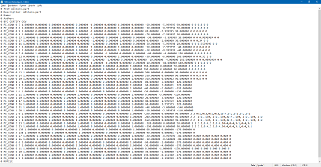
In figure 1.2 you can see the *.part file with all connectivity elements you can choose from the menu. There are 43 of them. Sorted by ID1. You can see the similarity between these elements. Only the seventh and eights block is different. I guess the above file format also applies to these files (more or less).

Figure 1.2: Connectivity file format for all connectivity elements you can pick from task bar
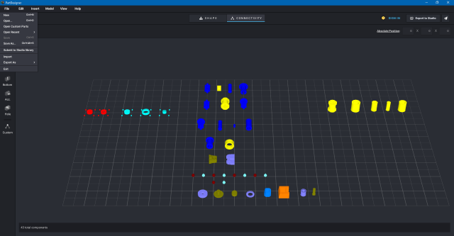
In figure 1.3 you can see all connectivity elements in the connectivity editor (sorted by group).

Figure 1.3: Connectivity elements in Part Designer
Hope the helps.
Best,
Gabe
maybe the *.conn file format is already known but in case its not you can find the description below. I’m also referring partly to the thread “Studio Connectivity Data“ where the question was asked how the *.conn file format is defined.
Connectivity files, e.g., the file definition is actually not too complicated to understand. However, it is more complicated as the collision files just because there are more of them and they are encrypted.
It is true that Part Designer converts the *.conn files -contrary to the *.col files- to a binary format (due to whatever reason). But this does not mean that you cannot access the information, you just have to use a trick. If you generate a part file in Part Designer and store it as *.part it contains all information about the brick. The geometry, the connectivity info and -hidden in the part geometry- the collision data. To see the connectivity info in human-readable format only thing you have to do: Start with a new part but only add connectivity elements (no geometry). In the part editor you will see an empty workspace but in the connectivity editor you can see the connectivity element. If you store this part now as *.part you can open and read it in a text editor (the conversion to binary takes places during export; not internally). From here it is rather a matter of changing the individual values/variables in *.part file and check what are the consequences. Below an image from the STUD connectivity element e.g. the file format:
Figure 1.1: Connectivity file format for the STUD connectivity element (associated *.part file)
I’ve been playing around with these values and compared it with the other connectivity elements. What I’ve found out so far:
First block: 0 (always the same)
Second block: PE_CONN (always the same, mostly likely a meta command; Part Editor Connectivity maybe)
Third block: ID1 (group ID see figure 1.2 below)
Fourth block: ID2 (element ID see figure 1.2 below)
Fifth block: 1 0 0 0 1 0 0 0 1 (always the same, Transformation matrix)*
Sixth block: XYZ (Position of the element)
Seventh block: 2 2 (always the same; geometry data aka visual representation of the element)**
Eight block: 3:1,0:4,3:1,0:4,10:4,0:4,3:1,0:4,3:1 (always the same; geometry data aka visual representation of the element)***
* For other elements not always the identity matrix; see figure 1.2
** Lateral size. If you change it from 2 2 to 1 1 it has half the size. But any other value does not work
*** Most complicated one. I guess it describes or are related the geometry of the connectivity element itself (squares in the corner, disc in the center and the connection lines). If you change 10:4 to 20:4 for example the disc changes its form from a disc to a ring. Some of the numbers fit roughly to the size of the connectivity element.
One can argue that during the export Part Editor adds additional data but I’ve also checked this. I’ve generated a *.part file with connectivity elements and exported it to Studio. The associated connectivity file (*.conn) I’ve opened in Part Editor and saved it as *.part again. If the exporter from PE adds additional data to the *.conn file these files should be different but there are the same (I’m assuming PE does not remove data during import).
In figure 1.2 you can see the *.part file with all connectivity elements you can choose from the menu. There are 43 of them. Sorted by ID1. You can see the similarity between these elements. Only the seventh and eights block is different. I guess the above file format also applies to these files (more or less).
Figure 1.2: Connectivity file format for all connectivity elements you can pick from task bar
In figure 1.3 you can see all connectivity elements in the connectivity editor (sorted by group).
Figure 1.3: Connectivity elements in Part Designer
Hope the helps.
Best,
Gabe


