Part x351 (41850) - Body, Racers Driver


Part x351 (41850) - Body, Racers Driver
#1

.png   x351.png (Size: 36.1 KB / Downloads: 549)
Hiya! I made a model of part x351 (or 41850 on other sites than bricklink), imported it into Bricklink's Part Designer and exported it to LDRAW format.
I read on the website I needed to write an e-mail to Orion Pobursky but was unable to find his e-mail address.
Feel free to let me know if there's something I need to fix, because I'm not sure what stuff is required and what is not.

- Jasper "JappaWakka" Speelman


Attached Files
.dat   x351.dat (Size: 169 KB / Downloads: 4)
Reply
RE: Part x351 (41850) - Body, Racers Driver
#2
Question 
Apparently there's a lot of invalid lines but I'm not sure what is invalid exactly.... I added some of the metadata but it seems to be the rest causing problems... can someone help me figure it out?
Also x351 is apparently not supported, so I changed it to the alternative part number 41850.


Attached Files
.dat   41850.dat (Size: 169.08 KB / Downloads: 6)
Reply
RE: Part x351 (41850) - Body, Racers Driver
#3
i could polish it and upload it to the tracker in your name but im busy rn
Reply
RE: Part x351 (41850) - Body, Racers Driver
#4
(2024-11-05, 13:32)Jasper Speelman Wrote: Apparently there's a lot of invalid lines but I'm not sure what is invalid exactly.... I added some of the metadata but it seems to be the rest causing problems... can someone help me figure it out?
Also x351 is apparently not supported, so I changed it to the alternative part number 41850.

Nice work there! I really like to finally have this part available Smile

Regarding the errors, most of it seems to be caused by the usual Stud.io export mess-ups. It can be very easily fixed in LDraw Parts Editor (at least it seems so).

The meta data should look something like this:

0 Body, Racers Driver
0 Name: 41850.dat
0 Author: Jasper Speelman [JappaWakka]
0 !LDRAW_ORG Unofficial_Part
0 !LICENSE Licensed under CC BY 4.0 : see CAreadme.txt

0 BFC CERTIFY CCW

A few more issues I found thus far:
*edge lines (Line Type 2) should be reworked, there are a few missing or misplaced I would say
*Conditional Lines (Line Type 5) are missing entirely, those are needed to make the round areas look 'smooth' (use Edger2, then manually check for errors)
*many triangles could be merged to quadrilaterals (use Rectifier from LDPE)
*the neck connector pin should probably be replaced by a cylinder primitive

Most of this can be done with LDraw Parts Editor (LDPE):
https://sourceforge.net/projects/partcreator/

br, Chris

EDIT:
Also, mirroring this part seems like a good idea. It's entirely symmetrical I guess?
Reply
RE: Part x351 (41850) - Body, Racers Driver
#5
(2024-11-05, 13:32)Jasper Speelman Wrote: Apparently there's a lot of invalid lines but I'm not sure what is invalid exactly.... I added some of the metadata but it seems to be the rest causing problems... can someone help me figure it out?
Also x351 is apparently not supported, so I changed it to the alternative part number 41850.

Looking at the file here's the problem:
Code:
3 16 6.696 0.000 -16.000 6.696 -4.369 -16.000 16.000 0.000 -16.000 0.000000 0.000000 0.000000 0.000000 0.000000 0.000000

All your triangles (the lines that begin with 3) should have 10 numbers after the "3" (1 for the color and 3 X,Y,Z coordinates for a total of 10), but instead they have 6 extra numbers. The Parts Tracker checks all lines for proper syntax so this is why the submit is rejecting your part.
Reply
RE: Part x351 (41850) - Body, Racers Driver
#6
Another little nitpick would be the y-coordinate of the neck connector:


I would assume that this is meant to be 'in system', meaning the y-value should be exactly 24 LDU not 24.006 LDU.

This would apply to the entire flat 'neck' area. Did you measure this value yourself?

Unfortunatley I can not access one of mine to compare at the moment Confused
Reply
RE: Part x351 (41850) - Body, Racers Driver
#7
(2024-11-05, 14:09)Chris Böhnke Wrote: Another little nitpick would be the y-coordinate of the neck connector:


I would assume that this is meant to be 'in system', meaning the y-value should be exactly 24 LDU not 24.006 LDU.

This would apply to the entire flat 'neck' area. Did you measure this value yourself?

Unfortunatley I can not access one of mine to compare at the moment Confused
That's a valid nitpick, I didn't measure stuff because blender doesn't measure things in ldu.
Reply
RE: Part x351 (41850) - Body, Racers Driver
#8
(2024-11-05, 14:00)Chris Böhnke Wrote: Nice work there! I really like to finally have this part available Smile

Regarding the errors, most of it seems to be caused by the usual Stud.io export mess-ups. It can be very easily fixed in LDraw Parts Editor (at least it seems so).

The meta data should look something like this:

0 Body, Racers Driver
0 Name: 41850.dat
0 Author: Jasper Speelman [JappaWakka]
0 !LDRAW_ORG Unofficial_Part
0 !LICENSE Licensed under CC BY 4.0 : see CAreadme.txt

0 BFC CERTIFY CCW

A few more issues I found thus far:
*edge lines (Line Type 2) should be reworked, there are a few missing or misplaced I would say
*Conditional Lines (Line Type 5) are missing entirely, those are needed to make the round areas look 'smooth' (use Edger2, then manually check for errors)
*many triangles could be merged to quadrilaterals (use Rectifier from LDPE)
*the neck connector pin should probably be replaced by a cylinder primitive

Most of this can be done with LDraw Parts Editor (LDPE):
https://sourceforge.net/projects/partcreator/

br, Chris

EDIT:
Also, mirroring this part seems like a good idea. It's entirely symmetrical I guess?
Those are useful tips. How do I mirror a part because I did make it symmetrical yes. And how do I add a cylinder primitive?
Reply
RE: Part x351 (41850) - Body, Racers Driver
#9
(2024-11-05, 13:54)Jeff Jones Wrote: i could polish it and upload it to the tracker in your name but im busy rn

its almost done
Reply
RE: Part x351 (41850) - Body, Racers Driver
#10
(2024-11-05, 14:20)Jeff Jones Wrote: its almost done

Oooo exciting!
Reply
RE: Part x351 (41850) - Body, Racers Driver
#11
im done with that part time to polish this up
Reply
RE: Part x351 (41850) - Body, Racers Driver
#12
(2024-11-05, 14:16)Jasper Speelman Wrote: Those are useful tips. How do I mirror a part because I did make it symmetrical yes. And how do I add a cylinder primitive?

Mirroring:

You would need 2 files for this:
41850.dat (the actual part, but it doesn't contain the raw geometric data)
41850s01.dat (a sub-part file, containing the actual geometry)

Using the program of your choice just delete all vertices on either the left or right side of your model, so there should be a clean cut along the plane of symmetry and save this as 41850s01.dat. Then have a file 41850.dat only containing the metadata and enter two lines like this:

1 16 0 0 0 1 0 0 0 1 0 0 0 1 s\41850s01.dat        //The left side
1 16 0 0 0 -1 0 0 0 1 0 0 0 1 s\41850s01.dat       //The right side

Subfiles always start with linetype "1". By keeping the transformation matrix "empty" (0 0 0 1 0 0 0 1 0 0 0 1) you asure that the main part keeps the origin of your halfed sub-part (and all other properties as well).

In the second line just turn the first x-value of the rotation matrix from 1 to -1 to have that one mirrored.

Primitives:

Primitives work very similar to the above. Use line type 1 and then input the required values in the transformation matrix. The advantage here is that it reduces the number of lines in the file, makes the cylinder more easy to modify and allows for different resolutions in most viewers.

1) Delete the existing cylinder geometry (but remember the actual position)
2) Cylinder primitives are set with their origin in the center top, so enter the original coordinates as the first 3 values, in your case this would be: 0 -32 0 (with the height accuracy already adjusted)
3) The first and third triplet of values afterwards change the radius (default is 1 LDU). Since you want a radius of 6, this gives 6 0 0 and 0 0 6 respectively.
4) Finally adjust the height in the second triplet: 0 8 0

Using the 4-4cylc primitive (full 360° cylinder which has top but no bottom surface and edges on both ends) gives you this line:
1 16 0 -32 0 6 0 0 0 8 0 0 0 6 4-4cylc.dat

The official documentation on primitives can be found here: https://wiki.ldraw.org/wiki/Primitives_R...ensional_2

While it's probably not 100% necessary for this part, I would still advise to use a matching "anti-circle" at the bottom around it, to avoid T-junctions and gaps:
1 16 0 -24 0 6 0 0 0 1 0 0 0 6 4-4ndis.dat
You would then have to realign the remaining vertices to this new square (including the mid points!)
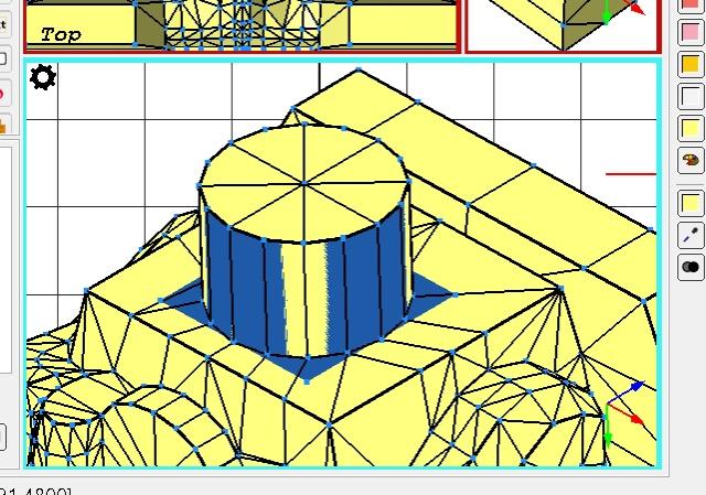
   

You can then repeat this process for the underside of the pin Wink
Reply
RE: Part x351 (41850) - Body, Racers Driver
#13
(2024-11-05, 14:47)Jeff Jones Wrote: im done with that part time to polish this up

How's it going? Smile
Reply
RE: Part x351 (41850) - Body, Racers Driver
#14
(2024-11-05, 17:31)Chris Böhnke Wrote: Mirroring:

You would need 2 files for this:
41850.dat (the actual part, but it doesn't contain the raw geometric data)
41850s01.dat (a sub-part file, containing the actual geometry)

Using the program of your choice just delete all vertices on either the left or right side of your model, so there should be a clean cut along the plane of symmetry and save this as 41850s01.dat. Then have a file 41850.dat only containing the metadata and enter two lines like this:

1 16 0 0 0 1 0 0 0 1 0 0 0 1 s\41850s01.dat        //The left side
1 16 0 0 0 -1 0 0 0 1 0 0 0 1 s\41850s01.dat       //The right side

Subfiles always start with linetype "1". By keeping the transformation matrix "empty" (0 0 0 1 0 0 0 1 0 0 0 1) you asure that the main part keeps the origin of your halfed sub-part (and all other properties as well).

In the second line just turn the first x-value of the rotation matrix from 1 to -1 to have that one mirrored.

Primitives:

Primitives work very similar to the above. Use line type 1 and then input the required values in the transformation matrix. The advantage here is that it reduces the number of lines in the file, makes the cylinder more easy to modify and allows for different resolutions in most viewers.

1) Delete the existing cylinder geometry (but remember the actual position)
2) Cylinder primitives are set with their origin in the center top, so enter the original coordinates as the first 3 values, in your case this would be: 0 -32 0 (with the height accuracy already adjusted)
3) The first and third triplet of values afterwards change the radius (default is 1 LDU). Since you want a radius of 6, this gives 6 0 0 and 0 0 6 respectively.
4) Finally adjust the height in the second triplet: 0 8 0

Using the 4-4cylc primitive (full 360° cylinder which has top but no bottom surface and edges on both ends) gives you this line:
1 16 0 -32 0 6 0 0 0 8 0 0 0 6 4-4cylc.dat

The official documentation on primitives can be found here: https://wiki.ldraw.org/wiki/Primitives_R...ensional_2

While it's probably not 100% necessary for this part, I would still advise to use a matching "anti-circle" at the bottom around it, to avoid T-junctions and gaps:
1 16 0 -24 0 6 0 0 0 1 0 0 0 6 4-4ndis.dat
You would then have to realign the remaining vertices to this new square (including the mid points!)


You can then repeat this process for the underside of the pin Wink
Chris Böhnke, I can't make any sense of this LDPartEditor tool. It's the most confusing 3d software I've ever seen. I don't think I can reliably use this.
I did figure out a way to have a better, more clean export from Blender using the ExportLDraw addon, which I've included in the attachments.
It already has the lines (although I can't find a way to add a conditional line myself) and smooth shading set properly. I also made sure some key vertices are rounded to whole LDUs.
Could this be useful? I really need some help getting this right.


Attached Files
.dat   41850.dat (Size: 326 bytes / Downloads: 2)
.dat   41850s01.dat (Size: 79.91 KB / Downloads: 4)
Reply
RE: Part x351 (41850) - Body, Racers Driver
#15
(2024-11-11, 12:58)Jasper Speelman Wrote: Chris Böhnke, I can't make any sense of this LDPartEditor tool. It's the most confusing 3d software I've ever seen. I don't think I can reliably use this.
I did figure out a way to have a better, more clean export from Blender using the ExportLDraw addon, which I've included in the attachments.
It already has the lines (although I can't find a way to add a conditional line myself) and smooth shading set properly. I also made sure some key vertices are rounded to whole LDUs.
Could this be useful? I really need some help getting this right.

for the stud
instead of this
Quote:1 16 0 -32 0 6 0 0 0 8 0 0 0 6 4-4cylc.dat
do this
Quote:1 16 0 -28 0 1 0 0 0 1 0 0 0 1 studa.dat
1 16 0 -28 0 6 0 0 0 4 0 0 0 6 4-4cyli.dat
Reply
RE: Part x351 (41850) - Body, Racers Driver
#16
(2024-11-11, 14:01)Jeff Jones Wrote: for the stud
instead of this
do this

Sure. Is the rest of the part okay?
Reply
RE: Part x351 (41850) - Body, Racers Driver
#17
(2024-11-11, 14:07)Jasper Speelman Wrote: Sure. Is the rest of the part okay?

i guess so
Reply
RE: Part x351 (41850) - Body, Racers Driver
#18
https://library.ldraw.org/parts/41803 (part)
https://library.ldraw.org/parts/41804 (subpart)
I submitted my part. It says I need 2 votes (on both the part and the subpart). Who can vote? Admins? Other part authors? What happens when they received the required number of votes?
Also I was wondering: as Bricklink's Studio 2.0 uses the LDraw library for its parts, who will add the connections and collision data? I definitely can't submit them through the LDraw Part Tracker.
Reply
RE: Part x351 (41850) - Body, Racers Driver
#19
Stud.io isn't maintained by LDraw.org but rather Bricklink/Lego.

This means the Stud.io collision/connectivity files will be added by them, when the will add your part to Stud.io (which may or may not happen, old parts get added quite inconsistently). So this is nothing you have to worry about.

Regarding the Parts Tracker, the people who can vote are Part Reviewers. Assuming everything is fine with your part and you get the 2 required votes, the part's status changes to "Admin Review", which is basically just a second review phase. After it passes this phase, it will usually be included in the next official parts update.

So if the part is okay, there is nothing more for you to do on that regard. Just check regularly if anybody makes a vote or comment until it's official.

If there are problems with the part, the reviewers will tell you about, so you can change it Wink .
Reply
RE: Part x351 (41850) - Body, Racers Driver
#20
(2024-11-11, 17:28)Chris Böhnke Wrote: Stud.io isn't maintained by LDraw.org but rather Bricklink/Lego.

This means the Stud.io collision/connectivity files will be added by them, when the will add your part to Stud.io (which may or may not happen, old parts get added quite inconsistently). So this is nothing you have to worry about.

Regarding the Parts Tracker, the people who can vote are Part Reviewers. Assuming everything is fine with your part and you get the 2 required votes, the part's status changes to "Admin Review", which is basically just a second review phase. After it passes this phase, it will usually be included in the next official parts update.

So if the part is okay, there is nothing more for you to do on that regard. Just check regularly if anybody makes a vote or comment until it's official.

If there are problems with the part, the reviewers will tell you about, so you can change it Wink .
Okay thank you Big Grin
Reply
RE: Part x351 (41850) - Body, Racers Driver
#21
Quote:you should get rid of the center vertices of straight edges... (merge to other vertices)
and the LDraw specs use somewhat "ideal" values on connections, so look to get the outer corners to nice round values.
for example, the corners are at 16.048 and 20.06, try to get these to 16 and 20.
same for the "neck" connection point, instead of -24.072 use -24
to do that, try using the LDPE

I don't know what to do or how to do it. LDPE is unusable to me. Nothing works like it should and it's stressing me out.
Reply
RE: Part x351 (41850) - Body, Racers Driver
#22
(2024-11-11, 19:23)Jasper Speelman Wrote: I don't know what to do or how to do it. LDPE is unusable to me. Nothing works like it should and it's stressing me out.

thats normal, LDPE is somewhat of a homebrew (by Nils Schmidt, he is also here in the forum)...

some instructions for you:

.png   VertexMod.png (Size: 16.16 KB / Downloads: 375)
select a vertex (either by clicking it or drag open a rectangle)
   
then use Actions -> Merge to nearest Vertex

and it plops to the nearest one (if that one isnt the right one, undo and manually move it closer by editing the values)
Reply
RE: Part x351 (41850) - Body, Racers Driver
#23
I think what Rene means is something like this:
   

A single line should only have 2 vertices on it. You probably have to puzzle a bit to get this arranged correctly with the connecting geometry, but it should be possible. There might be a few exception an additional vertex is  unavoidable, but those shown can be merged for example.

Also you should rebuild the neck area using a primitive (blue) and then add new triangles (red):
   

(Please note there are still a few unneccessary vertices in this image that should be merged)

Hope this helps a bit.
Reply
RE: Part x351 (41850) - Body, Racers Driver
#24
(2024-11-13, 9:25)Chris Böhnke Wrote: I think what Rene means is something like this:


A single line should only have 2 vertices on it. You probably have to puzzle a bit to get this arranged correctly with the connecting geometry, but it should be possible. There might be a few exception an additional vertex is  unavoidable, but those shown can be merged for example.

Also you should rebuild the neck area using a primitive (blue) and then add new triangles (red):


(Please note there are still a few unneccessary vertices in this image that should be merged)

Hope this helps a bit.

That does help a lot! I'll get to work Big Grin
Reply
RE: Part x351 (41850) - Body, Racers Driver
#25
When you have all the surfaces the right way up I would recommend you to start figuring out an excellent tool called Edger2.

Now there are many (manually?) added condlines in your file which have bad control point.
This makes them show up to soon, or to late, and don't give the wanted result.

Delete all the condlines you have first. Add new ones with the tool.

Click on Tools.. and choose Edger2. This opens a menu of settings for the tool. All you need to start with are the 2 marked dropdowns. 


If you choose Include Unmatched Edges the tool will add a red edge line where an edge line is missing.
Since you are working on a mesh divided in 2 halves it might be better to choose Exclude Unmatched Edges.

The other dropdown will set the scope for the tool. 
Choose File if you only want to add missing lines in the file you're working on, or File+subfiles if you want the tool to search deeper in the part structure for missing edge and condlines.
Leave all the rest in default settings.

Click OK and the tool will add what is missing.

When you are satisfied with the settings you can use the quick button Edger2, next to the Tool.. menu, to trigger the tool to add condlines.
That button will use the settings from the Edger2 tool menu.
Reply
RE: Part x351 (41850) - Body, Racers Driver
#26
made some photos of my two parts on a 2x4 plate (composed into 1 image)
all outer sides are slanted and coarse like the standard 2xX slopes


Attached Files Thumbnail(s)
   
Reply
RE: Part x351 (41850) - Body, Racers Driver
#27
(2024-11-19, 11:18)Rene Rechthaler Wrote: made some photos of my two parts on a 2x4 plate (composed into 1 image)
all outer sides are slanted and coarse like the standard 2xX slopes

bottom pic?
is it actually hollow with no tube?
Reply
RE: Part x351 (41850) - Body, Racers Driver
#28
no need for bottom pic, bottom is quite ok (and upskirting isnt)
the small inverted cylc is also correct, there is no big bottom tube like the 2x2 brick, there is just the rim
Reply
RE: Part x351 (41850) - Body, Racers Driver
#29
(2024-11-19, 11:18)Rene Rechthaler Wrote: made some photos of my two parts on a 2x4 plate (composed into 1 image)
all outer sides are slanted and coarse like the standard 2xX slopes

what do you mean exactly with coarse? like... rough? how do I make them rough?
Reply
RE: Part x351 (41850) - Body, Racers Driver
#30
Finding surfaces to subfile is always good, but dividing flat quads into 2 symetrical halves is never good practice.
Here is an example of useless vertices that should be avoided.


Try to remove these surfaces from the subfile, and then add them in the top level as full quads, spanning from left to right side.
Reply
RE: Part x351 (41850) - Body, Racers Driver
#31
(2024-11-19, 21:14)Magnus Forsberg Wrote: Finding surfaces to subfile is always good, but dividing flat quads into 2 symetrical halves is never good practice.
Here is an example of useless vertices that should be avoided.


Try to remove these surfaces from the subfile, and then add them in the top level as full quads, spanning from left to right side.

Actually, those vertices may be there avoid t-junctions where the base meets the top. (I can't tell for sure if this is true.) There is certainly reasonable debate about how much effort should go into avoiding t-junctions, but saying that they are useless is wrong if they do indeed prevent t-junctions.
Reply
RE: Part x351 (41850) - Body, Racers Driver
#32
I'm not sure what to do now... Two people are saying two different things and I don't know what t junctions are.
Reply
RE: Part x351 (41850) - Body, Racers Driver
#33
(2024-11-19, 21:14)Magnus Forsberg Wrote: Finding surfaces to subfile is always good, but dividing flat quads into 2 symetrical halves is never good practice.
Here is an example of useless vertices that should be avoided.


Try to remove these surfaces from the subfile, and then add them in the top level as full quads, spanning from left to right side.

That would result in these part files (I made backups just in case)
It's not ideal when it comes to modeling, because it's not symmetrical....


Attached Files
.dat   41850s01.dat (Size: 45.19 KB / Downloads: 3)
.dat   41850.dat (Size: 4.76 KB / Downloads: 3)
Reply
RE: Part x351 (41850) - Body, Racers Driver
#34
(2024-11-21, 14:56)Jasper Speelman Wrote: I'm not sure what to do now... Two people are saying two different things and I don't know what t junctions are.

This page explains t-junctions:

https://wiki.ldraw.org/wiki/T-Junction

As mentioned, I don't know if the extra quads here are present to prevent a t-junction or not.
Reply
RE: Part x351 (41850) - Body, Racers Driver
#35
guess its ok if the last triangle is to the center vertex of a cyl prim at the middle, and everything else are long quads across
-> the quads infront and at the back of the neck connector could get rearranged
(and now the feet are too sloped, the outer feet vertexes should be at +-19 -17 -19, the front slope is the same as the bottom of the rear slope -> all of the outer slopes have the same gradient)
Reply
RE: Part x351 (41850) - Body, Racers Driver
#36
(2024-11-21, 15:24)Jasper Speelman Wrote: That would result in these part files (I made backups just in case)
It's not ideal when it comes to modeling, because it's not symmetrical....

But you can make them symmetrical...

You have already correctly found, and avoided a T-junction here, by adding a triangle and a quad:
   

But you should expand the search for symmetrical quads.
These are also divided:
   

Start at the cylinder. Split the surface into triangles. The pink triangle should be in the subfile, making the subfile symmetric.
All the green surface should then be in the main file.
   

Many more surfaces are divided in your part. I just made this to show an example.

Two symmetrical quad is equal to 4 triangles to render.
In my example the quads are replaced by 3 triangles. One less to render.
Reply
RE: Part x351 (41850) - Body, Racers Driver
#37
How is this?


Attached Files
.dat   41850.dat (Size: 5.85 KB / Downloads: 10)
.dat   41850s01.dat (Size: 43.5 KB / Downloads: 10)
Reply
RE: Part x351 (41850) - Body, Racers Driver
#38
(2024-11-22, 9:23)Jasper Speelman Wrote: How is this?

Looks good, there's just one more quad near the neck in the front that could be converted.
Actually that would turn two quads into 3 triangles so I understand why you may not want to do that,
Reply
RE: Part x351 (41850) - Body, Racers Driver
#39
(2024-11-22, 17:31)Mark Kennedy Wrote: Looks good, there's just one more quad near the neck in the front that could be converted.
Actually that would turn two quads into 3 triangles so I understand why you may not want to do that,

I couldn't find a good way to change those 2 quads without simply turning them into 4 triangles because otherwise you'd have a t intersection. I'll upload it to the part tracker soon then, if Rene is okay with those feet vertices. I would like feedback on the sides of the seat/legs because I didn't know if they needed to be angled the same as the feet and back of the seat.
Reply
RE: Part x351 (41850) - Body, Racers Driver
#40
(2024-11-22, 18:09)Jasper Speelman Wrote: I couldn't find a good way to change those 2 quads ......

Try this:
   

.. and you can remove one triangle.
Reply
RE: Part x351 (41850) - Body, Racers Driver
#41
(2024-11-22, 18:40)Magnus Forsberg Wrote: Try this:


.. and you can remove one triangle.

Yeah that triangle in the center can be removed because otherwise you'd have a vertex halfway on a straight line. I'll fix it later. Thanks Smile
Reply
RE: Part x351 (41850) - Body, Racers Driver
#42
In the main file you may want to change the line:
1 16 0 -24 17.307 -11.878 0 0 0 1 0 0 0 -1.269 rect2p.dat
to a regular rect so you won't need the edge lines in the subfile.
Also maybe move the 1-4cyls to the subfile.
Reply
RE: Part x351 (41850) - Body, Racers Driver
#43
(2024-11-23, 3:59)Mark Kennedy Wrote: In the main file you may want to change the line:
1 16 0 -24 17.307 -11.878 0 0 0 1 0 0 0 -1.269 rect2p.dat
to a regular rect so you won't need the edge lines in the subfile.
Also maybe move the 1-4cyls to the subfile.

I don't quite understand what you mean with the rect thing as that was done by the rectifier tool, what is the difference between rect2p and a regular rect and also how do I know what edge lines you're talking about
Reply
RE: Part x351 (41850) - Body, Racers Driver
#44
(2024-11-23, 6:27)Jasper Speelman Wrote: I don't quite understand what you mean with the rect thing as that was done by the rectifier tool, what is the difference between rect2p and a regular rect and also how do I know what edge lines you're talking about

Here are all the primitives:
https://wiki.ldraw.org/wiki/Primitives_R...imensional
Reply
RE: Part x351 (41850) - Body, Racers Driver
#45
(2024-11-23, 7:36)Magnus Forsberg Wrote: Here are all the primitives:
https://wiki.ldraw.org/wiki/Primitives_R...imensional

Ah, thanks! Applied the latest suggestions, will submit to the part tracker! Big Grin
Reply
RE: Part x351 (41850) - Body, Racers Driver
#46
Hello: allow me to introduce a pic that show some arrangements to this part


The colors 11 and 12 are in the subfile, and color 19 in main file.

If you do it be warned to modify the subfile accordingly.
It's only a suggestion; others may or may not concord.
Reply
RE: Part x351 (41850) - Body, Racers Driver
#47
Hello: a pic showing one of the unmatched vertices. It is on the shaft,


.png   Unmatched vertices.png (Size: 1.9 KB / Downloads: 86)

Also, I post my code of the shaft (from the above post):

Goes in subfile:
Code:
4 16 9.446 -17 -19 7.536 -8.479996 -18.4344101 6.425 -3.524 -19 6.425 -3.524 -19.762
4 16 7.536 -8.479996 -18.4344101 9.446 -17 -19 9.05799 -15.269 -15.933 7.98 -10.461 -17.106
3 16 0 -19.714 -13.607 1.06065 -18.610758 -13.607 3.534 -19.983 -13.607
3 16 1.06065 -8.480996 -18.4344101 4 -10.461 -17.106 1.5 -10.461 -17.069
4 16 4 -10.461 -17.106 1.06065 -8.480996 -18.4344101 7.536 -8.479996 -18.4344101 7.98 -10.461 -17.106
4 16 1.06065 -8.480996 -18.4344101 0 -3.701 -19 6.425 -3.524 -19 7.536 -8.479996 -18.4344101
4 16 3.643 -21.517 -13.607 1.799 -22.212 -13.607 0 -22.483 -13.607 0 -19.714 -13.607
4 16 0 -19.714 -13.607 3.534 -19.983 -13.607 4.654 -20.133 -13.607 3.643 -21.517 -13.607
4 16 1.5 -10.461 -17.069 4 -10.461 -17.106 4 -10.46 -13.607 1.5 -10.46 -13.607
4 16 1.06065 -18.610758 -13.607 1.5 -15.947385 -13.607 3.263 -17.452 -13.607 3.534 -19.983 -13.607
4 16 3.263 -17.452 -13.607 1.5 -15.947385 -13.607 1.5 -10.46 -13.607 4 -10.46 -13.607
1 16 0 -10.461 -17.069 1.5 0 0 0 6.76 0 0 0 -1.931 8\1-4cyls.dat
3 16 1.06065 -10.461 -18.4344101 1.5 -10.461 -17.069 1.06065 -10.892331 -18.4344101
4 16 1.06065 -10.461 -18.4344101 1.06065 -10.892331 -18.4344101 0 -11.071 -19 0 -10.461 -19
3 16 1.06065 -16.378716 -14.9724101 1.5 -15.947385 -13.607 1.06065 -18.62889794 -13.607
4 16 0 -19.714 -13.607 0 -16.557385 -15.538 1.06065 -16.378716 -14.9724101 1.06065 -18.62889794 -13.607

Goes in main file:
Code:
3 16 6.425 -3.524 -19 0 -3.701 -19 -6.425 -3.524 -19
4 16 6.425 -3.524 -19 -6.425 -3.524 -19 -6.425 -3.524 -19.762 6.425 -3.524 -19.762
1 19 0 -15.947385 -13.607 -1.5 0 0 0 5.48639 -0.61 0 -3.462 -1.931 8\2-4cyli.dat

If you use the codes, you can delete some conditional lines.
But as before, these is a suggestion; you are the author of the part.
Reply
RE: Part x351 (41850) - Body, Racers Driver
#48
Can I assume you understand what a condline is?
An edgeline that is only visible under certain conditions.


On this image one condline is made visible. The line is placed between the vertices A and B. (One vertex, many vertices).
The conditions for the line is visualized as two other imaginary lines; A-C and A-D.
(Note that this condline have one bad controlpoint, D. To be correct it has to connect to either E or F)

The code for a condline is made of 4 points.
5 <colour> x1 y1 z1 x2 y2 z2 x3 y3 z3 x4 y4 z4

Here is a real one from your part
5 24 3.263 -17.452 -16.378 6.4 -17.495 -16.771 5.979 -19.995 -15.973 7.908 -10.278 -17.106

How do I make it visible?

.png   Image 005.png (Size: 9.45 KB / Downloads: 75)

Activate the Line tool found here, and click on an edge between 2 surfaces.
If there is a condline, it will become visible as this:


Is there a way to find missing condlines?
Activate the Cond Line Mode.  All condlines are now made visible, and orange.


How do I make a new condline manually?
Activate the Create Condline Tool


.png   Image 008.png (Size: 30.22 KB / Downloads: 74)

and then grab all the wanted vertices; A, B, C and D. In that order. One at a time
Remember vertex C and D must be from the 2 surfaces between which you want to create a condline.


.png   Image 009.png (Size: 25.21 KB / Downloads: 74)

Here I'm trying to grab point C

LDPE will not create a condline if the angle between the 2 surfaces are judged as to small.
When you are making condlines the tool sticks to the first, or second vertex. You can release that by pressing Esc and grab a different vertex.

Now, to illustrate what I said in my review.
You need to add condlines in the red squares, and the vertices in the green rings don't match.
And LDPE can't grab a vertex correctly, if the vertices don't match.

   
Reply
RE: Part x351 (41850) - Body, Racers Driver
#49
I think I got it! I had to merge some vertices for some reason apparently and I also fixed the scaling/postioning of the unalligned primitive.
   
Subpart


Main part
Reply
RE: Part x351 (41850) - Body, Racers Driver
#50
Thank you guys for your help and guidance! I'm very proud of the result and super happy that my part has finally be certified!
It took like a month of work, and I'm probably never gonna do this again, but I'm glad I got to contribute to the community and the library!
You guys are awesome! Big Grin
Reply
« Next Oldest | Next Newest »


Forum Jump:


Users browsing this thread: 1 Guest(s)