LDCad Advanced rotation techniques


Advanced rotation techniques
#1
I feel like I'm under-using LDCad's advanced rotation capabilities. But instead of a question, I think it's easier to just give an example—and sort of a challenge. Smile

In the attached test file I have an oddly-shaped piece that I want to rest on the ground, here represented by a nice big tile. This part has four lower extremities, all with different y-values, and to be realistic it would need to rest against the lowest three of them. What's the best way to do this using LDCad?
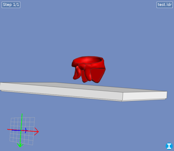
   
.ldr   test.ldr (Size: 173 bytes / Downloads: 2)

Here's how I would approach it:
  1. Find the lowest point and set it as the rotation center. You could use a helper part or a marker, but how do you find the point itself? Easiest way would be if you could directly select the vertex—LDCad can't do this, but LDPE can.
  2. Find the next lowest point the same way, then using more helper parts and some trigonometry (or the handy, but unofficial, right angle calc script), rotate the part so this hits the ground.
  3. For the final rotation, select the third low point, and rotate around a vector formed by the first two points. LDCad does allow custom vector rotation—but how do I find the vector and enter it into the rotation dialog?
Even better would be if you could select all three points at once and use them to define a plane, then set the part's absolute rotation just once so that this plane matches the ground plane. This could probably be scripted, but there's still the problem of selecting the points in the first place.

Is there a better way? How would you approach this problem?


(Can't attach the .lua file for the angle script, but here it isSmile
Code:
function onRun()

  local sel=ldc.selection()
  if sel:getRefCount()<3 then
    return
  end

  local a=sel:getRef(1):getPos()
  local b=sel:getRef(2):getPos()
  local c=sel:getRef(3):getPos()

  local ba=a-b
  local bc=c-b

  local n=bc:getCross(ba)
  n:normalize()

  local bb1=n:getSignedAngle(ba, bc)
  local bb2=math.deg(math.acos(bc:getLength()/ba:getLength()))

  local angle=-(bb1-bb2)
  ldc.setClipboardText(angle)

  ldc.dialog.runMessage(angle)
end

function register()

  local macro=ldc.macro('Right angle rotation calc')
  macro:setEvent('run', 'onRun')
end

register()
Reply
RE: Advanced rotation techniques
#2
(2022-07-22, 13:40)N. W. Perry Wrote: Is there a better way? How would you approach this problem?
With alpha 2 of 1.7 you could use script to find the 'bottom' coordinates.

Then use those to make a plane, which then can be used to construct an orientation matrix.

The only real problem is finding those resting points inside the mesh's unique points list.
Reply
RE: Advanced rotation techniques
#3
(2022-07-22, 22:04)Roland Melkert Wrote: With alpha 2 of 1.7 you could use script to find the 'bottom' coordinates.

Then use those to make a plane, which then can be used to construct an orientation matrix.

The only real problem is finding those resting points inside the mesh's unique points list.

Indeed, it would be really slick if we could directly access the mesh points!

But assuming I know a couple of the points, is there a way to find the vector between them through the GUI? I guess via selection info (taking angle values from each of the orthogonal views)?
Reply
RE: Advanced rotation techniques
#4
(2022-07-23, 1:25)N. W. Perry Wrote: Indeed, it would be really slick if we could directly access the mesh points!

But assuming I know a couple of the points, is there a way to find the vector between them through the GUI? I guess via selection info (taking angle values from each of the orthogonal views)?

The attached script levels (3 items of) the selection.

core of the script:
Code:
for i=1,3 do
  ref[i]=sel:getRef(i)
    pos[i]=ref[i]:getPos()
  end
 
  local xx=(pos[2]-pos[1]):getNormalized()
  local zzTmp=(pos[3]-pos[1]):getNormalized()
  local yy=xx:getCross(zzTmp)
  local zz=xx:getCross(yy)
 
  local ori=ldc.matrix()
  ori:setOriCols(xx, yy, zz)

The script takes 3 items from the selection and use them to get a plane normal.
Then it uses one of the 2 triangle vectors as the x-axis to build an orientation matrix.

You'll have to rotate it around Y afterwards to get it on its final place.

The really cool thing would be to analyze the mesh (possible in 1.7 Alpha 2a) to get those 3 points automatically.


Attached Files
.zip   levelItems.zip (Size: 862 bytes / Downloads: 2)
Reply
RE: Advanced rotation techniques
#5
I think there are fundamental geometric problems with the "select all three points at once then rotate" approach. This is because you can't specify "the three lowest points" without also specifying an absolute rotation. If you select your three lowest points and then _change_ the orientation of the part, there's no guarantee that the new "three lowest points" are the same three points.

Owen.
Reply
RE: Advanced rotation techniques
#6
(2022-07-24, 1:34)Owen Dive Wrote: I think there are fundamental geometric problems with the "select all three points at once then rotate" approach. This is because you can't specify "the three lowest points" without also specifying an absolute rotation. If you select your three lowest points and then _change_ the orientation of the part, there's no guarantee that the new "three lowest points" are the same three points.

Owen.

Indeed, and another thing is that you won't always have a nice level plane. What if, instead, you need the part to rest against the inside of a box with studs on the bottom? So I think of a step-by-step approach:
  1. Move the part downwards until its lowest point hits the highest point of the "receiving" part.
  2. Locate the point of contact, and rotate around this until the second low point contacts the ground.
  3. Select the first and second points, get the vector between them, and rotate around this vector to find the third point.
This might still be automatable, but it would require analyzing the mesh of both parts and tracking the successive rotations. If a certain point becomes lower than the original lowest point, it has to become the new rotation center.

Still, I think there are certain cases where your eyes will tell you that a plane on one part can be rotated to match a plane on another, and if that's the case it's nice to have a one-step process.
Reply
RE: Advanced rotation techniques
#7
(2022-07-23, 19:20)Roland Melkert Wrote: The attached script levels (3 items of) the selection.

The script takes 3 items from the selection and use them to get a plane normal.
Then it uses one of the 2 triangle vectors as the x-axis to build an orientation matrix.

You'll have to rotate it around Y afterwards to get it on its final place.

The really cool thing would be to analyze the mesh (possible in 1.7 Alpha 2a) to get those 3 points automatically.

Nifty! So that makes the process:
  1. Set the part to be rotated at the origin, and place helper parts at its 3 low points—in this case determined by LDPE. (Hiding the ground tile for the moment…)
       
  2. Select the 3 helper parts and apply the script.
       
  3. Set the grid relative to the lowest helper part and copy its orientation. Set the main part's rotation center to the relative origin, then rotate it using the matrix option.
       
  4. Finally, translate everything upward so the helper parts are at y=0, then delete them. Voila! It's level.
       
So the only question now is, what happens if the ground isn't nice and smooth? Angel
   
Reply
RE: Advanced rotation techniques
#8
(2022-07-25, 2:50)N. W. Perry Wrote: Select the 3 helper parts and apply the script.
Set the grid relative to the lowest helper part and copy its orientation. Set the main part's rotation center to the relative origin, then rotate it using the matrix option.
You can also extend the script to apply the rotation to the whole selection instead of just the first 3 items.

(2022-07-25, 2:50)N. W. Perry Wrote: So the only question now is, what happens if the ground isn't nice and smooth? Angel
There's always room for improvement Smile
Reply
RE: Advanced rotation techniques
#9
(2022-07-25, 20:54)Roland Melkert Wrote: You can also extend the script to apply the rotation to the whole selection instead of just the first 3 items.

That's what I was thinking, any items beyond three would be rotated also—and it would take the first part in the selection as the rotation center, like usual?

Quote:There's always room for improvement Smile

Indeed. Smile  Maybe by selecting another three points, you could establish them as the "target" plane. Although, you probably wouldn't know those three points until you've worked out the rotation, so a stepwise approach is probably necessary for cases like those.

Only thing I'm still not sure of is, how can I find the XYZ values for this dialog:
   
Like if I want to select two helper parts, then rotate the main part around the vector connecting them?
Reply
RE: Advanced rotation techniques
#10
(2022-07-25, 21:32)N. W. Perry Wrote: Only thing I'm still not sure of is, how can I find the XYZ values for this dialog:

If you want to rotate around the x-as you would use vector 1,0,0 (or -1,0,0) just like scripts do.

The dialog was intended for using information from third parties whom often use these rotation vectors instead of an orientation matrices.
Reply
RE: Advanced rotation techniques
#11
(2022-07-26, 19:16)Roland Melkert Wrote: If you want to rotate around the x-as you would use vector 1,0,0 (or -1,0,0) just like scripts do.

The dialog was intended for using information from third parties whom often use these rotation vectors instead of an orientation matrices.

Oh, I see, so that's a matrix row, not angles. Maybe that tool doesn't work the way I thought!
Reply
RE: Advanced rotation techniques
#12
(2022-07-26, 21:25)N. W. Perry Wrote: Oh, I see, so that's a matrix row, not angles. Maybe that tool doesn't work the way I thought!

The X, Y, and Z values in the dialog are not a matrix row. They are the coordinates of one endpoint of line segment representing a vector. (The other endpoint is implicitly 0,0,0.) The direction the vector points defines the axis of rotation, and the rotation angle defines the magnitude of the rotation. Note that the only thing that matters for this vector is the direction it points, not its own magnitude. So, 1,0,0 and 2,0,0 would produce the same results for a given angle, since both are aligned with the X axis.
Reply
RE: Advanced rotation techniques
#13
(2022-07-26, 23:03)Travis Cobbs Wrote: The X, Y, and Z values in the dialog are not a matrix row. They are the coordinates of one endpoint of line segment representing a vector. (The other endpoint is implicitly 0,0,0.) The direction the vector points defines the axis of rotation, and the rotation angle defines the magnitude of the rotation. Note that the only thing that matters for this vector is the direction it points, not its own magnitude. So, 1,0,0 and 2,0,0 would produce the same results for a given angle, since both are aligned with the X axis.

Well shoot, I always though matrix rows were vectors. But I'd never really thought in terms of coordinates before. (This is always my problem with this stuff: I learn specific concepts for specific tasks, but I'm always missing the important bits in the middle.)

So this means, to find the values for this dialog, I could simply select the first helper part and set the grid relative to it. Then, the coordinates of the second helper part would give me the XYZ values I need to rotate around a vector connecting them.

I think.
Reply
« Next Oldest | Next Newest »


Forum Jump:


Users browsing this thread: 1 Guest(s)