Hello everyone,
maybe the *.col file format is already known but in case its not you can find the description below. I’m also referring partly to the thread “Studio Connectivity Data“ where the question was asked how the *.col file format is defined.
Collider files e. g. the file definition is actually not too complicated to understand. I’ve not checked all *.col files in the Studio LDraw folder but some of them. Hence, I cannot tell you if the file format applies to all files, but it applies to the ones I’ve checked. Below a snapshot from the collider file for brick 3005.dat (named 3005.col).

Figure 1.1: Collider file for brick 3005.dat (1x1 Brick)
Each line in the *.col files describes one collision box. All lines (boxes) together form kind of collider brick. Whenever two of these collider bricks are touching each other, the associated brick went transparent in Studio which indicates a collision (if the function is activated in Studio).
The file format from one collision box is as follows:
First block: 9 (always the same)
Second block: 0 (always the same)
Third block: 1 0 0 0 1 0 0 0 1 (1st part of a transformation matrix; always the same)*
Fourth block: X Y Z (2nd part of the transformation matrix; position of the collision box)
Fifth block: W H L (size of the collision box)
Sixth block: null (always the same)**
* Some of the *.col files store this block as 1 instead of 1.000
** This block only exists in the earlier *.col files (at the same time Studio beta was launched; maybe a coincidence).
I’ve written a very simple and basic program that converts a *.col file into a *.ldr file using the box.dat primitive (one primitive for each collision box). The above file is then called 3005COL.ldr. In figure 1.2 below you can see the collider brick in red. In figure 1.3 I’ve superimposed the collider brick and the real brick itself (brick 3005 is drawn transparent for clarification).
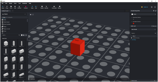
Figure 1.2: Collider brick for brick 3005
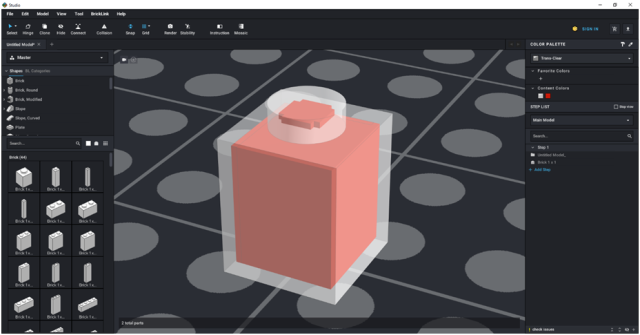
Figure 1.3: Collider brick and brick 3005 superimposed
One can see that the collider brick is a little bit smaller as the brick itself. This can be verified with Studio also. The collision warning does not occur directly after the bricks have contact but a little later. See figure series below.
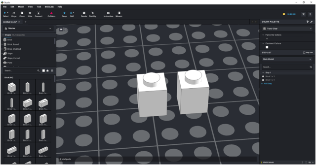
Figure 1.4: Two 1x1 bricks separated. Collision warning in Studio activated. No collision detected.
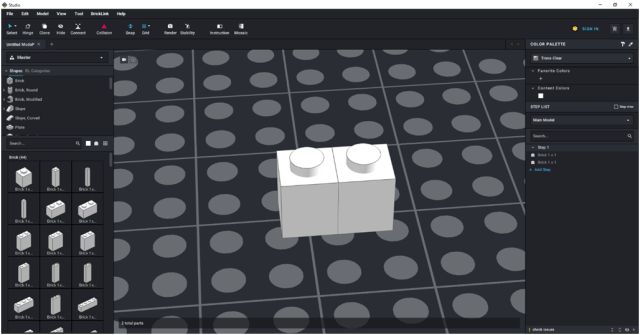
Figure 1.5: Two 1x1 bricks just touching each other. Collision warning in Studio activated. No collision detected.
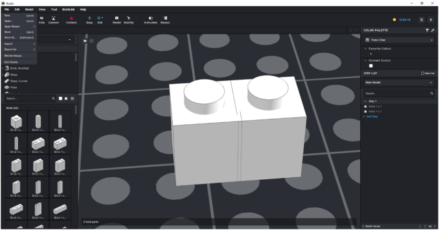
Figure 1.6: Two 1x1 bricks collided (they intersect a little bit). Collision warning in Studio activated. But no collision detected.
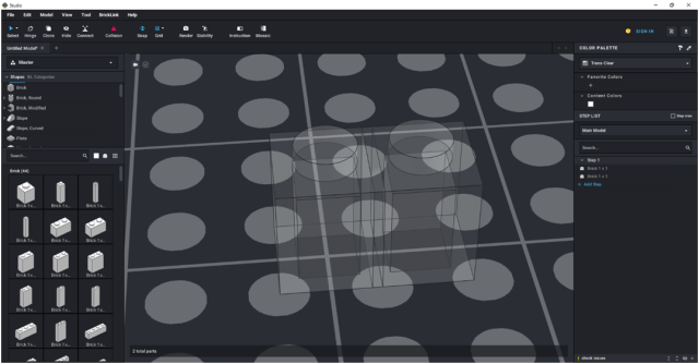
Figure 1.7: Two 1x1 bricks collided (they intersect a bit more). Collision warning in Studio activated. Now the bricks turn transparent to indicate a collision.
To show the geometry of more complex collider bricks, I’ve also converted the *.col files for part 10a (Baseplate 24 x 32), 64713 (Cone Spiral Jagged - Step Drill) and 59278 (Boat hull, Hull Unitary 74 x 18 x 7 with Light Bluish Gray Top). The first one is a part with multitude of studs, the second one a complex shaped part and the latter one of the largest file in the *.col folder. See images below.
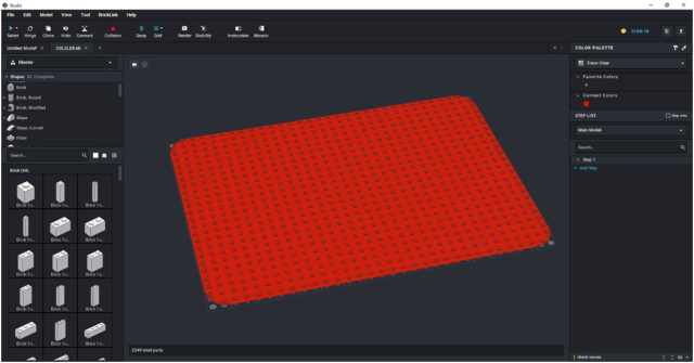
Figure 1.8: Collider brick for part 10a.dat (Baseplate 24 x 32)
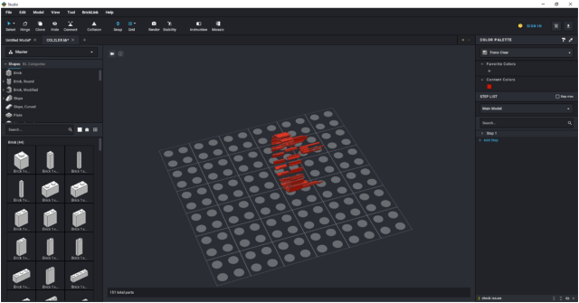
Figure 1.9: Collider brick for part 64713.dat (Cone Spiral Jagged - Step Drill)
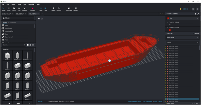
Figure 1.10: Collider brick for part 59278.dat (Boat hull, Hull Unitary 74 x 18 x 7 with Light Bluish Gray Top)
And some close ups from 10a.dat and 59278.dat.
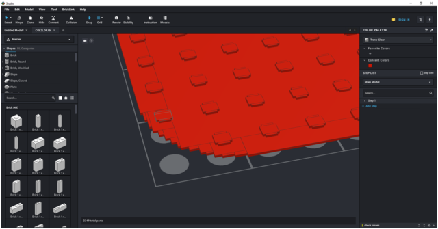
Figure 1.11: Close-up from the collider brick for part 10a.dat
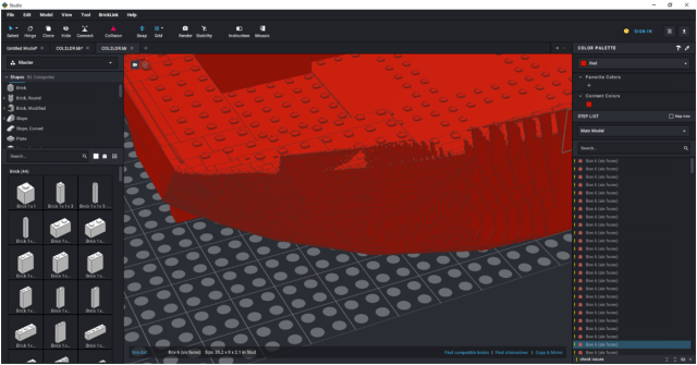
Figure 1.12: Close-up from the collider brick for part 59278.dat
Hope the above explanation helps to get an impression how studio calculates collisions.
Best,
Gabe
maybe the *.col file format is already known but in case its not you can find the description below. I’m also referring partly to the thread “Studio Connectivity Data“ where the question was asked how the *.col file format is defined.
Collider files e. g. the file definition is actually not too complicated to understand. I’ve not checked all *.col files in the Studio LDraw folder but some of them. Hence, I cannot tell you if the file format applies to all files, but it applies to the ones I’ve checked. Below a snapshot from the collider file for brick 3005.dat (named 3005.col).
Figure 1.1: Collider file for brick 3005.dat (1x1 Brick)
Each line in the *.col files describes one collision box. All lines (boxes) together form kind of collider brick. Whenever two of these collider bricks are touching each other, the associated brick went transparent in Studio which indicates a collision (if the function is activated in Studio).
The file format from one collision box is as follows:
First block: 9 (always the same)
Second block: 0 (always the same)
Third block: 1 0 0 0 1 0 0 0 1 (1st part of a transformation matrix; always the same)*
Fourth block: X Y Z (2nd part of the transformation matrix; position of the collision box)
Fifth block: W H L (size of the collision box)
Sixth block: null (always the same)**
* Some of the *.col files store this block as 1 instead of 1.000
** This block only exists in the earlier *.col files (at the same time Studio beta was launched; maybe a coincidence).
I’ve written a very simple and basic program that converts a *.col file into a *.ldr file using the box.dat primitive (one primitive for each collision box). The above file is then called 3005COL.ldr. In figure 1.2 below you can see the collider brick in red. In figure 1.3 I’ve superimposed the collider brick and the real brick itself (brick 3005 is drawn transparent for clarification).
Figure 1.2: Collider brick for brick 3005
Figure 1.3: Collider brick and brick 3005 superimposed
One can see that the collider brick is a little bit smaller as the brick itself. This can be verified with Studio also. The collision warning does not occur directly after the bricks have contact but a little later. See figure series below.
Figure 1.4: Two 1x1 bricks separated. Collision warning in Studio activated. No collision detected.
Figure 1.5: Two 1x1 bricks just touching each other. Collision warning in Studio activated. No collision detected.
Figure 1.6: Two 1x1 bricks collided (they intersect a little bit). Collision warning in Studio activated. But no collision detected.
Figure 1.7: Two 1x1 bricks collided (they intersect a bit more). Collision warning in Studio activated. Now the bricks turn transparent to indicate a collision.
To show the geometry of more complex collider bricks, I’ve also converted the *.col files for part 10a (Baseplate 24 x 32), 64713 (Cone Spiral Jagged - Step Drill) and 59278 (Boat hull, Hull Unitary 74 x 18 x 7 with Light Bluish Gray Top). The first one is a part with multitude of studs, the second one a complex shaped part and the latter one of the largest file in the *.col folder. See images below.
Figure 1.8: Collider brick for part 10a.dat (Baseplate 24 x 32)
Figure 1.9: Collider brick for part 64713.dat (Cone Spiral Jagged - Step Drill)
Figure 1.10: Collider brick for part 59278.dat (Boat hull, Hull Unitary 74 x 18 x 7 with Light Bluish Gray Top)
And some close ups from 10a.dat and 59278.dat.
Figure 1.11: Close-up from the collider brick for part 10a.dat
Figure 1.12: Close-up from the collider brick for part 59278.dat
Hope the above explanation helps to get an impression how studio calculates collisions.
Best,
Gabe


