RE: Part x351 (41850) - Body, Racers Driver
2024-11-25, 21:09 (This post was last modified: 2024-11-25, 21:12 by Magnus Forsberg.)
2024-11-25, 21:09 (This post was last modified: 2024-11-25, 21:12 by Magnus Forsberg.)
Can I assume you understand what a condline is?
An edgeline that is only visible under certain conditions.

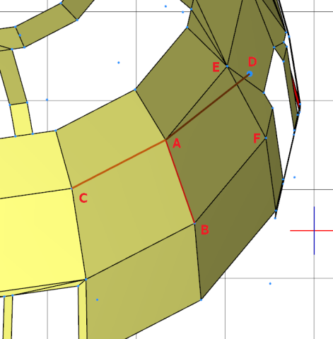
On this image one condline is made visible. The line is placed between the vertices A and B. (One vertex, many vertices).
The conditions for the line is visualized as two other imaginary lines; A-C and A-D.
(Note that this condline have one bad controlpoint, D. To be correct it has to connect to either E or F)
The code for a condline is made of 4 points.
5 <colour> x1 y1 z1 x2 y2 z2 x3 y3 z3 x4 y4 z4
Here is a real one from your part
5 24 3.263 -17.452 -16.378 6.4 -17.495 -16.771 5.979 -19.995 -15.973 7.908 -10.278 -17.106
How do I make it visible?
 Image 005.png (Size: 9.45 KB / Downloads: 81)
Activate the Line tool found here, and click on an edge between 2 surfaces.
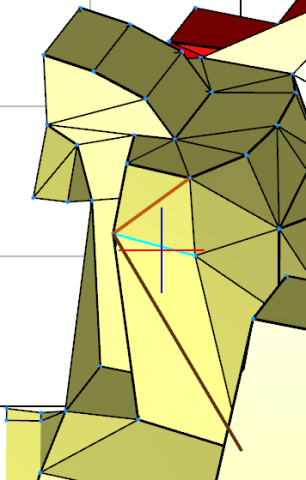
If there is a condline, it will become visible as this:

Is there a way to find missing condlines?
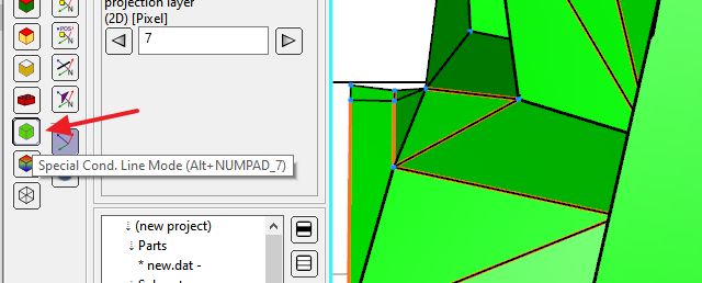
Activate the Cond Line Mode. All condlines are now made visible, and orange.

How do I make a new condline manually?
Activate the Create Condline Tool
 Image 008.png (Size: 30.22 KB / Downloads: 80)
and then grab all the wanted vertices; A, B, C and D. In that order. One at a time
Remember vertex C and D must be from the 2 surfaces between which you want to create a condline.
 Image 009.png (Size: 25.21 KB / Downloads: 80)
Here I'm trying to grab point C
LDPE will not create a condline if the angle between the 2 surfaces are judged as to small.
When you are making condlines the tool sticks to the first, or second vertex. You can release that by pressing Esc and grab a different vertex.
Now, to illustrate what I said in my review.
You need to add condlines in the red squares, and the vertices in the green rings don't match.
And LDPE can't grab a vertex correctly, if the vertices don't match.

An edgeline that is only visible under certain conditions.
On this image one condline is made visible. The line is placed between the vertices A and B. (One vertex, many vertices).
The conditions for the line is visualized as two other imaginary lines; A-C and A-D.
(Note that this condline have one bad controlpoint, D. To be correct it has to connect to either E or F)
The code for a condline is made of 4 points.
5 <colour> x1 y1 z1 x2 y2 z2 x3 y3 z3 x4 y4 z4
Here is a real one from your part
5 24 3.263 -17.452 -16.378 6.4 -17.495 -16.771 5.979 -19.995 -15.973 7.908 -10.278 -17.106
How do I make it visible?
 Image 005.png (Size: 9.45 KB / Downloads: 81)
Activate the Line tool found here, and click on an edge between 2 surfaces.
If there is a condline, it will become visible as this:
Is there a way to find missing condlines?
Activate the Cond Line Mode. All condlines are now made visible, and orange.
How do I make a new condline manually?
Activate the Create Condline Tool
 Image 008.png (Size: 30.22 KB / Downloads: 80)
and then grab all the wanted vertices; A, B, C and D. In that order. One at a time
Remember vertex C and D must be from the 2 surfaces between which you want to create a condline.
 Image 009.png (Size: 25.21 KB / Downloads: 80)
Here I'm trying to grab point C
LDPE will not create a condline if the angle between the 2 surfaces are judged as to small.
When you are making condlines the tool sticks to the first, or second vertex. You can release that by pressing Esc and grab a different vertex.
Now, to illustrate what I said in my review.
You need to add condlines in the red squares, and the vertices in the green rings don't match.
And LDPE can't grab a vertex correctly, if the vertices don't match.


